3.03 Circuit Lab: Ohm’s Law, Series and Parallel with a Multimeter
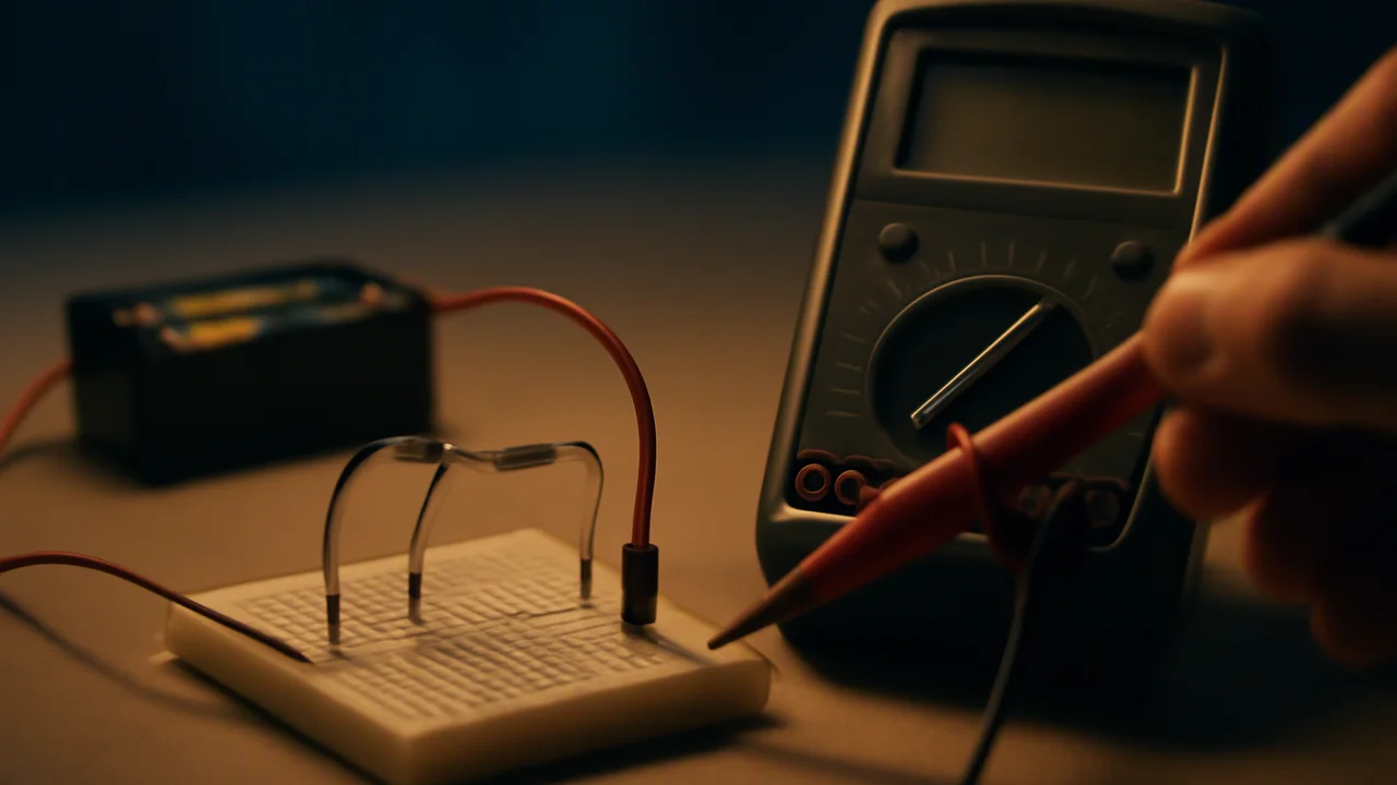
measure voltage and current with a multimeter, test Ohm’s law with an I-V graph, and use conservation of charge and energy to explain and calculate how current, voltage and energy divide in series and parallel circuits.
- I can identify and describe the boundaries of a system and explain how the reference level for potential energy is set to zero.
- I can quantify and express the initial energies of each component in a system using algebraic descriptions, including thermal, kinetic, and potential energies.
- I can describe and quantify energy flows into or out of a system using algebraic expressions, and I can calculate the total final energy of the system’s components.
- I can use algebraic descriptions of initial and final energy states, along with energy flows, to create a computational model based on the principle of conservation of energy.
- I can use a computational model to calculate the change in energy of one component in a system when I know the changes in energy of other components and the energy flows.
Phase 2: Investigate
Warm-Up ~5 min
Do Now. A string of holiday lights goes dark when one bulb fails, but the lamps in your kitchen do not. Sketch how each might be wired, then make the prediction.
A 330 Ω and a 470 Ω resistor are in series with a 6.0 V battery. Where is the current largest?
Instruction ~10 min
From charges to circuits. In lesson 3.01 charges sat still. In a circuit they move. Current I is the rate at which charge flows past a point, in amperes (1 A = 1 C/s). Voltage (potential difference) V is the energy each coulomb of charge gains or loses between two points, in volts (1 V = 1 J/C). A 6.0 V battery gives every coulomb that passes through it 6.0 J, and the circuit components take that energy back out as light, heat or motion. Resistance R, in ohms (Ω), measures how much voltage it takes to push a given current through a component.
Ohm’s law. For many materials at constant temperature (resistors, metal wires), current is proportional to voltage: V = IR. Worked example: 6.0 V across a 330 Ω resistor drives I = 6.0/330 = 18.2 mA. A filament bulb is not ohmic: its resistance rises as it heats up, so its I-V graph curves.
Energy and power. Each second, I coulombs each deliver V joules, so the power is P = IV = I2R = V2/R. The 330 Ω resistor on 6.0 V dissipates 6.02/330 = 0.109 W, safely under the 0.25 W rating of a common resistor. A 1,200 W toaster on a 120 V outlet draws 10 A: the same physics at 1,000 times the scale, which is why we never experiment with wall outlets.
Series circuits. Components in one loop carry the same current, and their voltages add up to the battery’s voltage (energy is conserved around a loop). Resistances add: 330 + 470 = 800 Ω. Worked example with 6.0 V: I = 6.0/800 = 7.5 mA; V1 = (7.5 mA)(330 Ω) = 2.475 V and V2 = 3.525 V, which add to 6.000 V. The larger resistor takes the larger share of the energy.
Parallel circuits. Each branch connects directly across the battery, so each gets the full 6.0 V, and the branch currents add at the junction (charge is conserved). I1 = 18.2 mA, I2 = 6.0/470 = 12.8 mA, total 30.9 mA. The equivalent resistance, 1/R = 1/330 + 1/470, is 193.9 Ω: less than either branch. Adding a branch lowers the total resistance and raises the battery current. That is why homes use parallel wiring (each appliance gets the full voltage) and why too many appliances on one circuit trip a breaker.
Using a multimeter. A voltmeter connects across a component (in parallel with it) and measures the energy per charge between its two ends. An ammeter connects in series, so the current must pass through it. Never connect an ammeter directly across a battery: it has almost no resistance, so a large current flows and blows the meter’s fuse. Start on the highest range and work down.
The lab’s evidence. An I-V graph for one resistor (illustrative):
| Cells | Measured V (V) | Measured I (mA) | R = V/I (Ω) |
|---|---|---|---|
| 1 | 1.55 | 4.79 | 324 |
| 2 | 3.08 | 9.32 | 330 |
| 3 | 4.61 | 14.17 | 325 |
| 4 | 6.12 | 18.66 | 328 |
The points lie on a straight line through the origin, the signature of Ohm’s law. The slope is 3.055 mA/V, so R = 1/slope = 327 Ω, 0.8% below the 330 Ω label, well within a resistor’s ±5% tolerance. In the series check, the measured voltages 2.51 V and 3.58 V add to 6.09 V against a battery reading of 6.12 V: energy is accounted for within the meter’s precision.
Misconceptions. (1) “Current is used up by the first resistor.” The current is the same all around a series loop; energy, not charge, is transferred. (2) “A battery supplies a fixed current.” It supplies a nearly fixed voltage; the current depends on the circuit. (3) “Electrons race around the circuit.” Their drift is slow (millimeters per second); the energy transfer is fast because the whole loop of charge starts moving at once.
Energy accounting as a computational model (HS-PS3-1). Treat the battery, wires and resistors as one system. Set the negative terminal as the zero of electric potential, just as you set the floor as the zero of gravitational potential energy in Unit 1. Each coulomb leaving the positive terminal carries 6.0 J it will give up on the way around. In the series circuit (7.5 mA for 60 s), the charge that flows is Q = It = (0.0075)(60) = 0.45 C. The battery’s chemical energy falls by QV = (0.45)(6.0) = 2.70 J. The 330 Ω resistor gains (0.45)(2.475) = 1.114 J of thermal energy and the 470 Ω resistor (0.45)(3.525) = 1.586 J. They add to 2.700 J: the model Ebattery = E1 + E2 balances exactly. If you know any two of the three terms, the model gives you the third.
Worked example: the most energy possible. A pack of four AA cells might store about 2.0 A·h at 6.0 V (illustrative capacity): (2.0 A)(3,600 s)(6.0 V) = 43,200 J. That is the maximum possible energy the pack can give the resistors, however they are wired. At 7.5 mA it would last 2.0/0.0075 ≈ 267 h. Our model assumes the voltage stays at 6.0 V the whole time and that the wires and the battery’s own internal resistance waste nothing. Your measured battery voltage of 6.12 V falling to 6.09 V under load shows that assumption is not quite true.
Lab procedure: Series and parallel circuits with a multimeter
Question. Does a resistor obey Ohm’s law, and how do current and voltage divide in series and parallel circuits?
Materials.
- Four AA cells in a battery holder with a switch (6 V maximum)
- Resistors of 330 Ω and 470 Ω (0.25 W), plus a small flashlight bulb in a holder
- A digital multimeter (voltage and 200 mA current ranges) with probe leads
- Alligator-clip leads or a solderless breadboard
Procedure.
- Ohm’s law: connect one 330 Ω resistor to one cell with the ammeter in series. Measure the voltage across the resistor and the current. Repeat with 2, 3 and 4 cells.
- Graph I against V and find the slope; compute R = 1/slope and compare with the color-code value.
- Replace the resistor with the flashlight bulb and repeat step 1. Compare the shape of its I-V graph.
- Series: connect the 330 Ω and 470 Ω resistors in series with 4 cells. Measure the current at three different points and the voltage across each resistor and across the battery.
- Parallel: connect the same resistors in parallel. Measure the voltage across each branch, each branch current and the total current.
- Compare every measurement with the value you predict from V = IR and the series and parallel rules, as a percent difference.
Data table.
| Cells | Measured V (V) | Measured I (mA) | R = V/I (Ω) |
|---|---|---|---|
| 1 | 1.55 | 4.79 | 324 |
| 2 | 3.08 | 9.32 | 330 |
| 3 | 4.61 | 14.17 | 325 |
| 4 | 6.12 | 18.66 | 328 |
| Rows above are illustrative. Add your own tables for the bulb, the series circuit (I at three points, V1, V2, Vbattery) and the parallel circuit (V across each branch, I1, I2, Itotal). | |||
Illustrative data set for the rest of the lab (Option B). Constructed teaching numbers from the same four-cell battery, not real measurements.
Flashlight bulb, same method as the resistor:
| Cells | Measured V (V) | Measured I (mA) | R = V/I (Ω) |
|---|---|---|---|
| 1 | 1.55 | 110 | 14.1 |
| 2 | 3.08 | 152 | 20.3 |
| 3 | 4.61 | 181 | 25.5 |
| 4 | 6.12 | 205 | 29.9 |
Series, 330 Ω and 470 Ω on four cells: current measured at three points 7.62, 7.60 and 7.63 mA; V1 = 2.51 V across the 330 Ω; V2 = 3.58 V across the 470 Ω; battery 6.12 V.
Parallel, the same two resistors on four cells: 6.05 V measured across each branch; I1 = 18.4 mA; I2 = 12.8 mA; total current 31.1 mA.
Analysis.
- Claim-evidence-reasoning: does the resistor obey Ohm’s law, and does the bulb? Use the shape of each I-V graph as evidence.
- Series: did the current stay the same at all three points, and did V1 + V2 equal the battery voltage? Explain each result with conservation of charge or energy.
- Parallel: did I1 + I2 equal the total current? Compute the equivalent resistance from your data and compare with 1/R = 1/R1 + 1/R2.
- Sources of error: the meter’s own resistance, the battery’s voltage dropping under load, and resistor tolerance. Which most affects your comparison, and in which direction?
Other routes to the same data. Choose one. All three earn full credit and end in the same I-V graphs, the same series and parallel comparisons and the same percent differences. Option A — build it with real parts. The procedure above with a multimeter, cells and resistors. Option B — the illustrative data sets in the data section above. No equipment and no internet needed. Graph I against V for the resistor and for the bulb, find the resistor’s R from the slope and show why the bulb’s rising R/V ratio means it is not ohmic. Then test the series data (does the current agree at all three points, and does V1 + V2 equal the battery reading?) and the parallel data (does I1 + I2 equal the total, and does 6.05 V ÷ 31.1 mA agree with 1/R = 1/330 + 1/470?). Give every comparison as a percent difference and decide which of the three error sources in the last analysis question best explains each one. Option C — PhET Circuit Construction Kit: DC. Use the sim block below as your laboratory. Build the resistor on 1.5, 3.0, 4.5 and 6.0 V and record the virtual ammeter’s reading each time; build the series circuit and measure the current at three points and the voltage across each resistor; build the parallel circuit and measure both branch currents and the total. Then answer every analysis question from your sim readings, and for the error question explain which of the three real-world error sources the simulation does not reproduce, and what that does to your percent differences. Cite the sim and the date you used it.
Guided Exercises ~15 min
Predict with V = IR first, then check against the lab data.
Independent Practice ~10 min
Write up the lab in your Grid Notebook.
Post your two I-V graphs. In 4–6 sentences, state whether the resistor and the bulb obey Ohm's law, give the resistor's R from the slope with its percent difference from the label, and explain the bulb's curve with what happens to the filament.
Build an energy model for your parallel circuit over 60 s: define the system and the zero of potential, write the algebraic equation for the battery's energy and each branch's energy, and calculate each term from your data. Then name one assumption that limits the model.
Closure ~5 min
Charge is conserved and so is energy: voltage tells us the energy each coulomb carries. Next lesson: does a current also make a magnetic field?
Exit ticket: why does adding another appliance in parallel at home raise the current in the wire from the breaker box?
How confident are you that you can I can measure V and I with a multimeter, test Ohm's law and calculate how energy divides in series and parallel circuits.
Teacher notes
Materials: see the lab list; one multimeter and battery pack per team. Reading: OpenStax Physics (high school), chapter 19, and OpenStax College Physics 2e, chapters 20–21 (CC BY 4.0).
Timing: Poly ran this lab over two 50-minute sessions. Run the Ohm’s law part and the series circuit in period one and the parallel circuit and analysis in period two, or pool class data in one period.
Listen for: “current is used up”; ammeter placed across a component; mA and A mixed in V = IR.
Support / stretch: give a pre-built spreadsheet with V = IR predictions. Stretch: estimate the battery’s internal resistance from the 6.12 V and 6.09 V readings.