2.03 Electromagnets and Moving Magnets
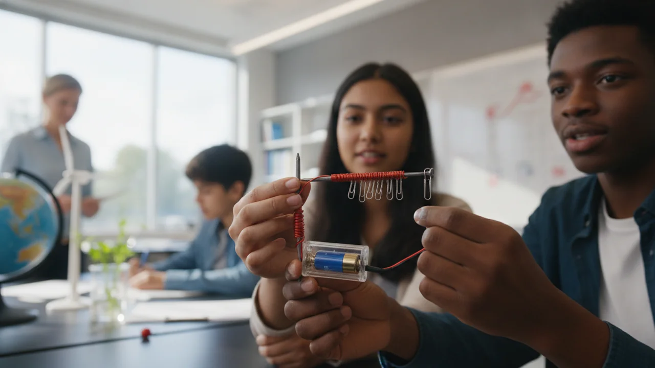
show that an electric current produces a magnetic field by building an electromagnet and measuring its strength, and show that a changing magnetic field produces a current in a coil.
- I can plan an investigation to collect data showing that a magnetic field appears only when electric current flows in a circuit.
- I can plan an investigation to collect data showing that an electric current is produced only when a magnetic field near a circuit changes.
- I can explain why the effects I observe are caused by electric current or changing magnetic fields, not just correlated, by describing the cause-effect relationships.
- I can include in my investigation plan the use of an electric circuit, a source of electrical energy, the shape and orientation of the wire, and the types and positions of detectors.
- I can describe how I will indicate or measure when electric current is flowing through the circuit.
- I can describe how I will indicate or measure the presence of a local magnetic field near the circuit, and how I will design a system to change the magnetic field in a nearby circuit and measure when the magnetic field is changing.
- I can measure and record electric currents and magnetic fields during my investigation.
Phase 2: Investigate
Warm-Up ~5 min
Do Now. A compass always points roughly north. Predict what would happen to the needle if you laid a wire carrying current just above it.
A magnet sits motionless inside a coil connected to a meter. The reading is
Instruction ~10 min
Two discoveries. In 1820, Hans Christian Ørsted noticed that a compass needle swung when he switched on a current in a nearby wire: an electric current produces a magnetic field. About ten years later, Michael Faraday showed the reverse: moving a magnet near a coil of wire produces a current in the coil, but only while the magnet is moving. Together these discoveries are the basis of every electric motor and every generator, including the ones in wind turbines. HS-PS2-5 asks you to plan and carry out an investigation that produces evidence for both.
Part A: current makes a magnetic field. Lay an insulated wire across the top of a compass, lined up north-south. Touch the wire’s ends to a D-cell for a few seconds: the needle swings. Reverse the battery and it swings the other way. The current creates a magnetic field that circles the wire. Wind the wire into a coil and each loop’s field adds to the next; wrap the coil around an iron nail and the iron’s own magnetic domains line up with the field, making it far stronger. That is an electromagnet.
Measuring strength. Count how many small paper clips the nail’s tip can lift in a chain or cluster. More coils should mean a stronger field. Keep the battery, the nail and the wire the same; change only the number of turns (10, 20, 30, 40). Make every coil the same way, tightly wound in one direction, and connect only for about 10 seconds per test, because the wire and battery warm up and the battery runs down. A fresh battery at the start and a check at the end tell you whether that happened.
Worked example 1: what to expect. Illustrative results: 10 turns lifted 2 clips, 20 turns 5, 30 turns 7, 40 turns 10. The graph of clips against turns rises roughly in a straight line: field strength increases with the number of turns. Counting clips is a coarse measurement (a clip is all or nothing), so repeat each test three times and average.
Part B: changing magnetic field makes a current. Wind about 100 turns of thin insulated wire around a cardboard tube and connect the ends to a digital multimeter set to its most sensitive current (μA or mA) or voltage (mV) range. No battery is used. Push a strong magnet into the tube: the reading jumps. Hold it still inside: the reading returns to zero. Pull it out: the reading jumps the other way. Move it faster: a bigger reading. The current appears only when the magnetic field through the coil is changing. That is electromagnetic induction.
Worked example 2: cause, not coincidence. Jamal’s meter read zero whenever the magnet was still and jumped every time it moved, with the sign flipping when the direction flipped. Because he controlled the motion and the reading followed every change, the evidence supports cause and effect: the changing field causes the current.
Planning the investigation. A good plan names the circuit, the energy source (D-cells for Part A; none for Part B), the shape and orientation of the wire, the detectors (compass, paper clips, multimeter) and where they sit, how you will know current is flowing, how you will change the field, and whether you work alone or as a team, with each member’s job.
Lab procedure: Building an Electromagnet and Inducing a Current. Materials: two D-cells in a holder; 2 m of insulated copper wire with stripped ends; a large iron nail (about 10 cm); small steel paper clips; a magnetic compass; a cardboard tube wound with about 100 turns of thin insulated wire; a digital multimeter; a strong bar or neodymium magnet that fits in the tube; goggles; masking tape.
- Lay a straight section of wire over the compass, aligned north-south. Connect the battery for 3 seconds and record the needle’s movement. Reverse the battery connections and repeat.
- Wrap 10 tight turns of wire around the nail, all in the same direction. Connect the battery, dip the nail tip into the paper clips, lift, count the clips, then disconnect. Repeat three times.
- Add turns to make 20, 30 and 40, repeating the three trials for each. Record the average number of clips.
- Connect the 100-turn coil to the multimeter on its most sensitive range. Push the magnet into the tube, hold it still, then pull it out. Record the reading during each motion.
- Repeat step 4 moving the magnet slowly and then quickly, and with the magnet turned around. Record the readings.
- Graph average clips lifted against number of turns.
| Turns | Clips trial 1 | Clips trial 2 | Clips trial 3 | Average |
|---|---|---|---|---|
| 10 | ||||
| 20 | ||||
| 30 | ||||
| 40 |
| Magnet motion (induction) | Meter reading (sign and size) |
|---|---|
| Pushed in slowly | |
| Held still inside | |
| Pulled out slowly | |
| Pushed in quickly | |
| Magnet reversed, pushed in |
No lab kit? Use the PhET Faraday’s Electromagnetic Lab (Electromagnet and Pickup Coil screens) to vary the number of loops and the magnet’s motion, with the provided video of the clip test.
Reading: OpenStax Physics (high school), chapter 20 (CC BY 4.0).
Guided Exercises ~15 min
Use your data tables. Every answer should cite a reading.
Independent Practice ~10 min
Evaluate your data.
Identify two sources of error in the clip test (for example, battery running down, uneven winding), how each would affect your graph, and whether your data is precise enough to support the claim.
Explain how a wind turbine could keep a current flowing continuously, using what you observed in Part B.
Closure ~5 min
Currents make fields, and changing fields make currents. Next class: how strong the electric force is compared with gravity.
Exit ticket: your meter read zero with the magnet still and 4 mV moving it fast. Explain why this is evidence of cause, not just correlation.
Teacher notes
Timing: Poly ran this lab over two 50-minute periods. Day 1: Part A and the clip graph. Day 2: Part B, the sim and the CER paragraphs.
Materials (per team): see the procedure. Pre-wind the 100-turn tubes; sand enamel off magnet-wire ends.
Listen for: “the magnet makes electricity by itself”; teams changing two variables at once; connecting the battery for too long.
Support / stretch: give a plan template with labeled boxes for circuit, source, detectors and roles. Stretch: graph induced voltage against magnet speed using slow-motion video.