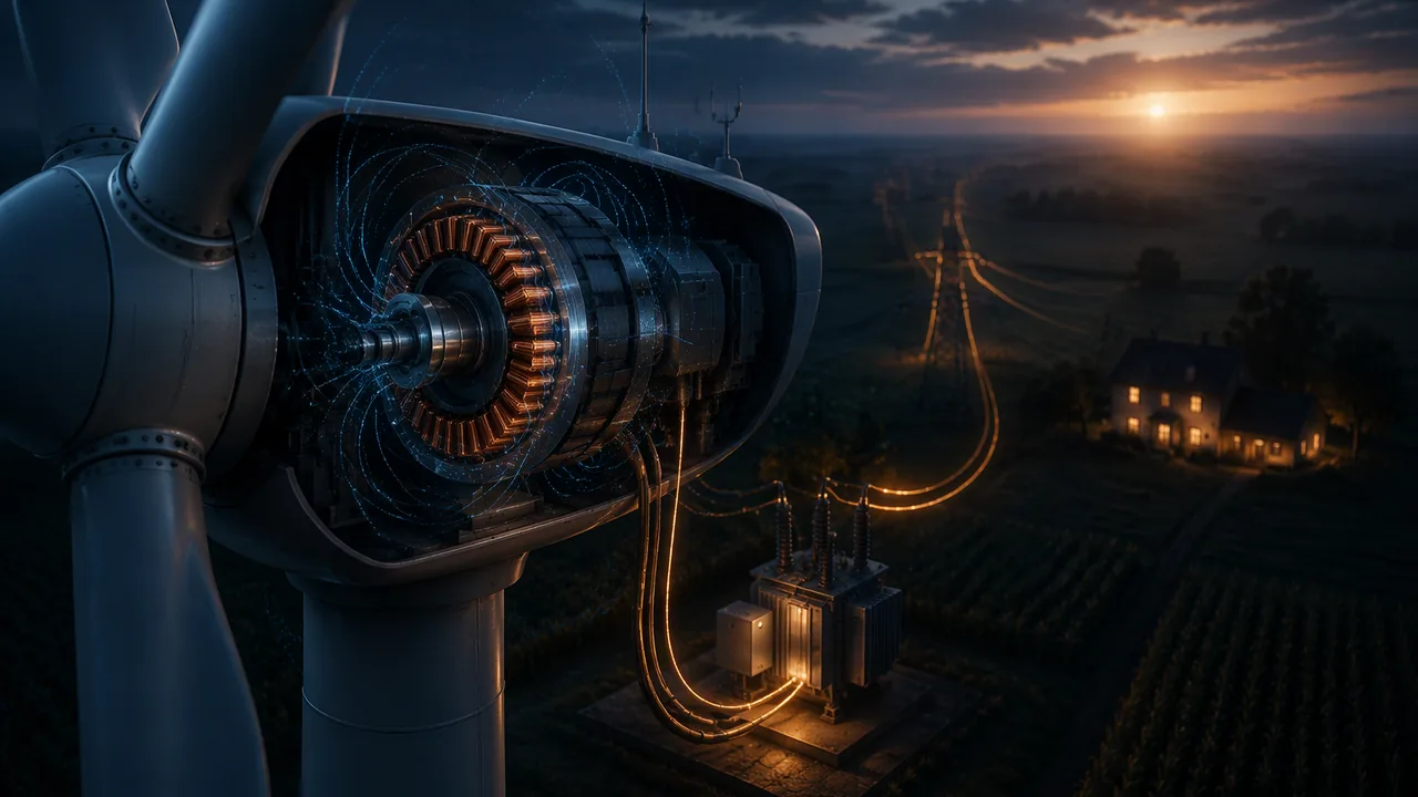
use electric-field and magnetic-flux models to calculate forces and energy changes, apply Faraday’s law to induction, and explain how generators, transformers and high-voltage transmission move energy from a wind farm to a home.
Instruction
Fields store energy and carry forces (9-12.PS3.C.1). Two charges or two magnets interact without touching because each is surrounded by a field. The electric field at a point is the force per coulomb a small positive test charge would feel there: E = F/q, in N/C. Around a point charge, E = kQ/r2, pointing away from a positive charge and toward a negative one.
Worked example: 2.0 cm from a +2.0 nC charge, E = (8.99 × 10⁹)(2.0 × 10⁻⁹)/(0.020)2 = 4.50 × 10⁴ N/C. An electron placed there feels F = eE = 7.20 × 10⁻¹⁵ N, toward the charge.
Energy in fields. When a charge moves with the field’s force, the field does work on it and the system’s potential energy falls; push it against the field and you store energy. Voltage measures this per coulomb: an electron crossing a 1.5 V cell gains eV = (1.602 × 10⁻¹⁹)(1.5) = 2.40 × 10⁻¹⁹ J. A proton accelerated from rest through 1,000 V reaches √(2eV/m) = 4.38 × 10⁵ m/s. The same energy bookkeeping you used for gravity in Unit 1 works here: the charges and their field form the system, and energy moves between the field and the charges’ kinetic energy.
Changing magnetic fields make currents. Michael Faraday found in 1831 that moving a magnet into a coil makes a current, but only while the field through the coil is changing. The magnetic flux through a loop is Φ = BA (field times area, for a field perpendicular to the loop). Faraday’s law: the induced voltage (emf) in a coil of N turns is
emf = NΔΦ/Δt
Worked example: a 100-turn coil 5.0 cm across has area π(0.025)2 = 1.96 × 10⁻³ m2. A magnet pushed in raises B through it from 0 to 0.050 T in 0.10 s: emf = (100)(0.050)(1.96 × 10⁻³)/0.10 = 98 mV. Push twice as fast and you get 196 mV. Hold the magnet still inside and you get zero.
Lenz’s law is energy conservation. The induced current makes its own magnetic field that opposes the change. Push a magnet in and the coil pushes back; you must do work, and that work becomes the electrical energy. If the induced current helped the magnet along, you would get energy from nothing.
Generators, turbines and transformers. A wind turbine in Atchison County, Missouri, turns a coil in a magnetic field (or magnets past coils), so the flux changes continuously and an alternating voltage is induced: the kinetic energy of the wind becomes electrical energy through the field. A transformer uses a changing current in one coil to induce a voltage in a second coil on the same iron core, with Vs/Vp = Ns/Np. A neighborhood transformer with 1000 primary turns and 20 secondary turns steps 12,000 V down to 240 V.
Why the grid uses high voltage. Power lines have resistance, and the power lost as heat is I2R. To deliver 100 MW through a line with 10 Ω of resistance (illustrative): at 115 kV the current is 870 A and the loss is 7.56 MW (7.6%); at 500 kV the current is 200 A and the loss only 0.40 MW (0.4%). Raising the voltage cuts the current, and the loss falls with the square of the current. Transformers make that possible, which is why the grid is AC.
Misconceptions. (1) “A strong magnet sitting in a coil makes a current.” Only a changing flux does. (2) “Transformers create energy by raising voltage.” Raising voltage lowers current; power in equals power out (minus losses). (3) “Field lines are real strings.” They are a model that shows direction and, by their spacing, strength.
📖 Read for this lesson
The reading opens over the lesson; close it to come back to exactly where you were. The checks below draw on it.
Lab: Induction coil mini-lab: a changing field makes a current
Question. What makes a voltage appear in a coil of wire near a magnet, and what makes it larger?
Materials
- About 5 m of thin insulated copper wire wound into a coil of 50-100 turns around a cardboard tube (or a ready-made coil)
- One or two strong bar or neodymium magnets that fit through the tube
- A digital multimeter on its lowest DC millivolt range (or a galvanometer)
- Tape and a ruler
- Neodymium magnets snap together hard and can pinch skin or shatter: handle one at a time and keep them apart; wear safety goggles.
- Keep magnets away from phones, cards, laptops and anyone with a pacemaker or other implanted device.
- No battery or outlet is used in this lab; the coil is connected only to the meter.
Procedure
- Connect the coil’s two ends to the multimeter on the millivolt setting.
- Push the magnet slowly into the coil and record the largest reading. Repeat quickly. Record the sign as well as the size.
- Pull the magnet out quickly and record. Then hold it still inside the coil and record.
- Turn the magnet around (other pole first) and repeat a fast push.
- Stack two magnets and repeat a fast push. If possible, wind a second coil with twice the turns and compare.
Data
| Action | Peak reading (mV) |
|---|---|
| slow push | 1.8 |
| fast push | 6.5 |
| fast pull out | −6.3 |
| magnet at rest inside | 0.0 |
| two magnets, fast | 12.1 |
| Illustrative readings; record three trials of each action and the sign of each reading. | |
Analysis
- Claim-evidence-reasoning: what must happen for the coil to produce a voltage? Use the at-rest reading and the speed comparison as evidence, and Faraday’s law as reasoning.
- Why did pulling out give the opposite sign from pushing in? Connect your answer to Lenz’s law and energy conservation.
- Hand speed varies from trial to trial. How large is that variation in your peak readings, and does the speed effect stand out from it?
If you cannot do this lab in person: Use PhET Faraday’s Law: move the magnet through the one-coil and two-coil setups at different speeds and read the voltmeter; the illustrative readings in the lesson also support every analysis question.
Formative check
Work through these before moving on. They are not graded — they tell you whether the standard below has landed yet.
Simulation & tools
Induced voltage and the speed of the magnet
Open Faraday’s Law with one coil and the voltmeter showing. (1) Push the magnet into the coil slowly, then quickly, and record the largest voltmeter swing each time. (2) Hold the magnet still inside the coil and record the reading. (3) Pull it out and note the sign. (4) Switch to two coils and repeat the fast push. Which changes make the voltage larger, and which make it zero? Explain each with emf = NΔΦ/Δt. No device: use the illustrative mini-lab readings in the lesson to answer the same questions.
Open in a new tab ↗ · PhET Interactive Simulations, University of Colorado Boulder · CC BY 4.0
A 100-turn coil of area 1.96 × 10⁻³ m2 sees its field rise from 0 to 0.050 T in 0.05 s. What is the induced emf?
Delivering 100 MW through a 10 Ω line at 500 kV needs A and loses MW as heat.
A magnet resting inside a coil keeps producing a current for as long as it stays there.
How confident are you that you can use field models to explain forces, energy changes and induction in generators and transformers?
Practice
Work these on paper or in your notebook, then open Check your answer. Aim for all of Fluency and Application; try at least one Challenge.
Printable version: this unit’s practice workbook (PDF)
Fluency
Build speed and accuracy with the core skill.
- A device draws 8 A from a 120 V supply. What power does it use, and how much energy in 1 hour?
Check your answer
Answer: 960.00 W; 3,456,000 J (0.960 kWh)P = VI; energy = Pt. - A device draws 2 A from a 12 V supply. What power does it use, and how much energy in 1 hour?
Check your answer
Answer: 24.00 W; 86,400 J (0.024 kWh)P = VI; energy = Pt. - Find the electric field 3.0 cm from a +5.0 nC charge.
Check your answer
Answer: 4.99 × 10⁴ N/C, away from the chargeE = kQ/r2. - A proton sits in a 2.0 × 10⁴ N/C field. Find the force and its acceleration (m = 1.673 × 10⁻²⁷ kg).
Check your answer
Answer: 3.20 × 10⁻¹⁵ N; 1.92 × 10¹² m/s2F = qE; a = F/m. - How much energy does an electron gain crossing a 12 V battery, in joules?
Check your answer
Answer: 1.92 × 10⁻¹⁸ JE = eV. - A 200-turn coil of area 3.0 × 10⁻³ m2 sees its field rise by 0.080 T in 0.050 s. Find the induced emf.
Check your answer
Answer: 0.96 Vemf = NΔ(BA)/Δt.
Application
Use the skill in context. Show your reasoning.
- A transformer has 600 primary turns and 50 secondary turns and is connected to 120 V AC. Find the secondary voltage. Would it work on a 6 V battery?
Check your answer
Answer: 10 V; noVs = VpNs/Np. A battery’s steady current makes no changing flux, so nothing is induced. - A wind farm sends 50 MW through lines with 8.0 Ω total resistance (illustrative). Compare the I2R loss at 69 kV and at 230 kV.
Check your answer
Answer: 4.20 MW vs 0.38 MWI = P/V; loss = I2R. - Explain with energy conservation why it gets harder to turn a generator’s crank when a bulb is connected.
Check your answer
Answer: The induced current’s field opposes the motion (Lenz’s law), so you must do work that becomes the bulb’s energy.With no bulb, no current flows and the crank turns freely.
Challenge
Stretch problems. Expect to think before you write.
- An electron starts from rest and is accelerated through 500 V. Find its final speed (m = 9.109 × 10⁻³¹ kg).
Check your answer
Answer: 1.33 × 10⁷ m/seV = ½mv2: energy moves from the field to the electron’s kinetic energy.
Review
Keep earlier skills sharp.
- A device takes in 1200 J and delivers 333 J of useful energy. What is its efficiency, and where did the rest go?
Check your answer
Answer: 27.8%; the other 867 J was transferred mostly as thermal energy to the surroundingsEfficiency = useful output / input × 100%. - A balloon holds 2.0 L at 20 °C. At constant pressure, what is its volume at 60 °C?
Check your answer
Answer: 2.27 LCharles’s law with absolute temperature: convert to kelvin (add 273.15) before dividing.
A Changing Field Makes a Current: The Induction Record, and the Wind Turbines of Atchison County
SLS constructed induction-coil record (illustrative, not laboratory measurements); USGS U.S. Wind Turbine Database API, Atchison County, Missouri (342 turbines); EIA Missouri wind capacity and generation for 2025 as compiled in rlp-psb-doe-wind-turbine-missouri; NIST CODATA 2022; retrieved Nov. 5, 2026 · SLS original, with public-domain U.S. government data
Why this reading. The lesson’s induction readings are one number per action with no trials, and its wind-farm figures are named but unsourced. Here is the mini-lab’s full record, three trials per action, so the analysis question about hand-speed variation can be answered; and the turbine-by-turbine figures for Atchison County, Missouri, from the U.S. Geological Survey’s national turbine database. The induction record is SLS teaching data constructed to behave like a 100-turn coil and a neodymium magnet, labeled illustrative; the wind-farm figures are not.
1. Induction coil mini-lab: the recorded readings
Coil: 100 turns of 26-gauge enameled wire on a 5.0 cm cardboard tube (area π(0.025)2 = 1.96 × 10⁻³ m2). Magnet: one 12 mm neodymium disc, or two stacked. Meter: digital multimeter on its 200 mV DC range; the meter updates about three times a second, so “peak reading” is the largest value seen during the motion, which understates the true peak. Sign: positive when the north pole enters first.
| Action | Peak reading, trials 1-3 (mV) | Mean (mV) |
|---|---|---|
| slow push (about 0.3 m/s) | 1.7, 1.9, 1.8 | 1.8 |
| fast push (about 1 m/s) | 6.2, 6.8, 6.5 | 6.5 |
| fast pull out | −6.1, −6.5, −6.3 | −6.3 |
| magnet at rest inside the coil | 0.0, 0.0, 0.0 | 0.0 |
| fast push, magnet turned end for end | −6.6, −6.3, −6.4 | −6.4 |
| two magnets stacked, fast push | 11.6, 12.5, 12.1 | 12.1 |
| second coil, twice the turns, fast push, one magnet | 12.4, 13.1, 12.8 | 12.8 |
Reading it. At rest inside the coil: zero, three times. The flux through the coil is large but not changing, and Faraday’s law needs a change. Pushing in fast gives 3.6 times the slow reading; the flux change is the same but the time is shorter. Pulling out reverses the sign: the flux is decreasing instead of increasing. Turning the magnet end for end also reverses the sign at the same speed: which pole enters decides the direction of the change. Two magnets roughly double the reading (12.1 against 6.5), because the field, and so the flux, is roughly doubled. Twice the turns roughly doubles it too (12.8 against 6.5): N in emf = NΔΦ/Δt.
Hand speed. The fast pushes scatter from 6.2 to 6.8 mV, about ±5%; the slow pushes from 1.7 to 1.9, about ±6%. The fast-slow difference is 4.7 mV, fifteen times the scatter. Speed is the effect; hand variation is the noise.
Faraday’s law check. If the fast push raised the field through the coil from 0 to 0.050 T in 0.10 s: emf = (100)(0.050)(1.96 × 10⁻³)/0.10 = 0.098 V = 98 mV; in 0.05 s, 196 mV. The meter read 6.5 mV, not 98, because a small disc magnet’s field is far below 0.050 T over the whole coil area and a slow meter misses the peak. The proportionalities, not the absolute number, are what this instrument can test.
2. The wind farms, from the U.S. Geological Survey
The U.S. Wind Turbine Database, kept by the U.S. Geological Survey with the Department of Energy’s national laboratories, lists every utility-scale turbine in the country with its project, model, rating, hub height and rotor diameter. For Atchison County, Missouri, in the state’s northwest corner on the Iowa and Nebraska borders, it lists 342 turbines with a combined rating of 800.0 MW in five projects:
| Project | Year online | Turbines | Capacity (MW) | Turbine models (rating, rotor diameter, hub height) |
|---|---|---|---|---|
| Cow Branch | 2008 | 24 | 50.4 | 24 × Vestas V120-2.2 (2.1 MW, rotor 120 m, hub 79 m) |
| Loess Hills | 2008 | 4 | 5.0 | 4 × Suzlon S64 (1.25 MW, rotor 64 m, hub 72 m) |
| Farmers City | 2009 | 73 | 146.0 | 73 × Gamesa G87-2.0 (2 MW, rotor 87 m, hub 78 m) |
| Rock Creek | 2017 | 150 | 300.0 | 150 × Vestas V110-2.0 (2 MW, rotor 110 m, hub 95 m) |
| Outlaw | 2021 | 91 | 298.6 | 51 × Vestas V150-4.2 (4.2 MW, rotor 150 m, hub 105 m); 22 × Vestas V120-2.2 (2.2 MW, rotor 120 m, hub 80 m); 18 × Vestas V110-2.0 (2 MW, rotor 110 m, hub 80 m) |
The database flags the Cow Branch machines as retrofitted in 2025; it now lists them as Vestas V120-2.2 models rated 2.1 MW. Two things in the table are induction physics. First, the ratings: the 2008 Loess Hills machines are 1.25 MW each and the largest 2021 Outlaw machines 4.2 MW, 3.36 times as much. A bigger generator sweeps more turns of copper through a stronger, faster-changing field, so emf = NΔΦ/Δt is larger and so is the current the generator can deliver. Second, the rotors: a 150 m rotor sweeps π(75)2 = 17,671 m2 of wind, (150/64)2 = 5.49 times the 3,217 m2 of a 64 m rotor, so it collects that much more of the wind’s kinetic energy to turn the generator against its Lenz’s-law push-back.
A turbine’s rating is its output in a strong, steady wind, not its average. Across all of Missouri’s wind farms, the U.S. Energy Information Administration reports 2,453.7 MW of operating wind capacity and 6,483,476 MWh generated in 2025, a capacity factor of 6,483,476 ÷ (2,453.7 × 8,760) = 30.2% (figures from the RLP Physical Science B reading on Missouri wind, retrieved the same day).
3. The lesson’s numbers, checked
Field 2.0 cm from +2.0 nC: (8.99 × 10⁹)(2.0 × 10⁻⁹)/(0.020)2 = 4.50 × 10⁴ N/C; on an electron, F = eE = 7.20 × 10⁻¹⁵ N. An electron crossing 1.5 V gains 2.40 × 10⁻¹⁹ J. A proton through 1,000 V reaches √(2eV/mp) = 4.38 × 10⁵ m/s (CODATA 2022 masses). Transformer: 1,000 to 20 turns steps 12,000 V to 240 V. Transmission of 100 MW through 10 Ω (illustrative resistance): at 115 kV, I = 870 A and I2R = 7.56 MW (7.6%); at 500 kV, I = 200 A and the loss is 0.40 MW (0.4%). Raising the voltage by 4.35 cut the current by 4.35 and the loss by 4.352 = 18.9.
Your turn
- From the induction table, compute the ratio of every row’s mean to the fast-push mean and match each ratio to the factor in emf = NΔΦ/Δt that changed.
- Estimate the uncertainty of the two-magnet mean from its three trials, and decide whether “doubling the magnets doubled the reading” is supported or only roughly supported.
- Rock Creek is 300.0 MW of 2.0 MW turbines. How many 100 kW turbines would the same rating have needed, and how many 4.2 MW Outlaw-size machines would it need? What changes in the generator’s flux and turns as machines grow?
- At a 30.2% capacity factor, how many megawatt-hours would Atchison County’s 800.0 MW produce in a year? Then compute the current needed to carry the full 800.0 MW at 345 kV and at 161 kV, and the ratio of I2R losses in the same conductor.
Sources: USGS, U.S. Wind Turbine Database (API query: Missouri, Atchison County) (energy.usgs.gov); EIA Open Data API, electricity/operating-generator-capacity (Missouri wind, 2025) (api.eia.gov); EIA Open Data API, electricity/electric-power-operational-data (Missouri, annual generation by fuel) (api.eia.gov); NIST CODATA 2022, proton mass (physics.nist.gov)