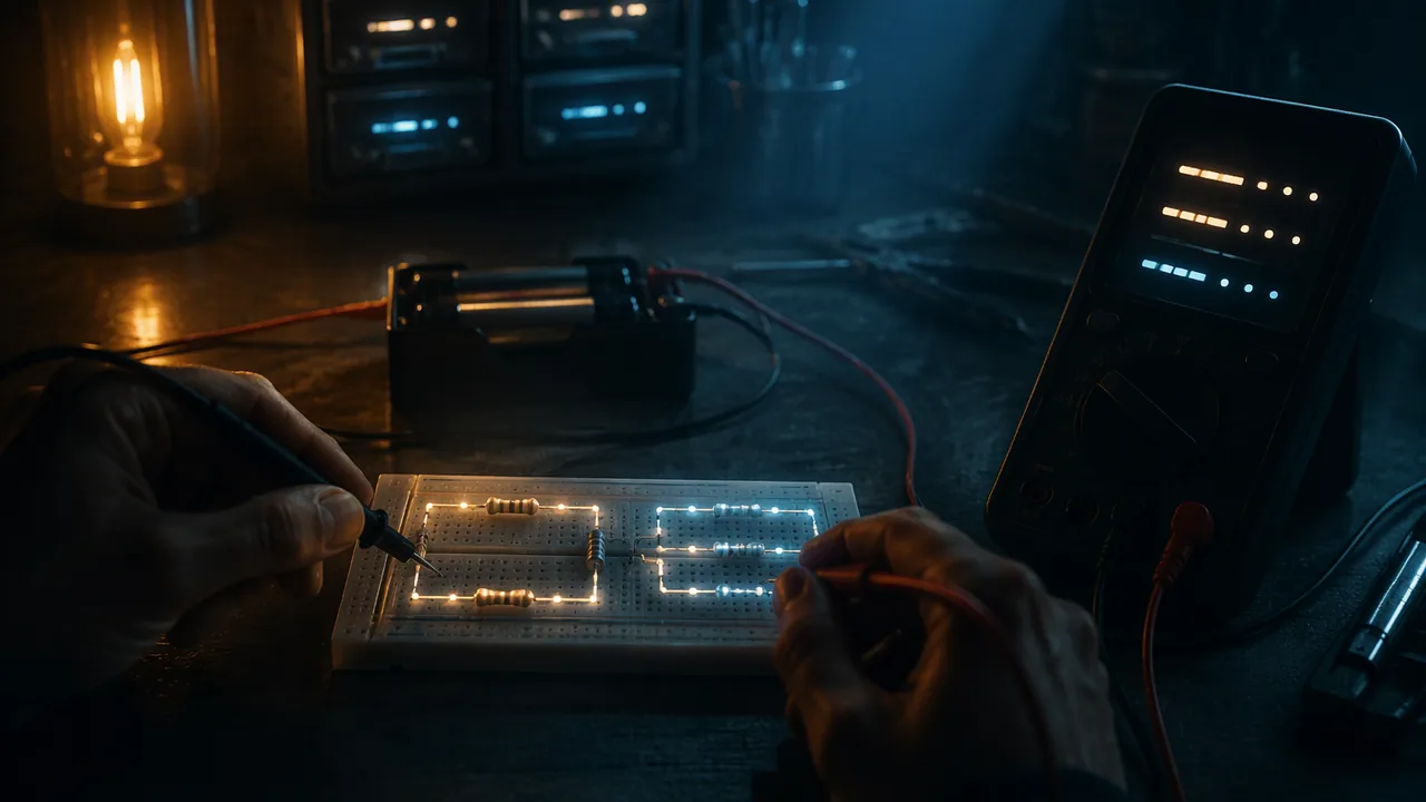
measure voltage and current with a multimeter, test Ohm’s law with an I-V graph, and use conservation of charge and energy to explain how current and voltage divide in series and parallel circuits.
Instruction
From charges to circuits. In Lesson 3.1 charges sat still. In a circuit they move. Current I is the rate at which charge flows past a point, in amperes (1 A = 1 C/s). Voltage (potential difference) V is the energy each coulomb of charge gains or loses between two points, in volts (1 V = 1 J/C). A 6.0 V battery gives every coulomb that passes through it 6.0 J, and the circuit components take that energy back out as light, heat or motion. Resistance R, in ohms (Ω), measures how much voltage it takes to push a given current through a component.
Ohm’s law. For many materials at constant temperature (resistors, metal wires), current is proportional to voltage: V = IR. Worked example: 6.0 V across a 330 Ω resistor drives I = 6.0/330 = 18.2 mA. A filament bulb is not ohmic: its resistance rises as it heats up, so its I-V graph curves.
Energy and power. Each second, I coulombs each deliver V joules, so the power is P = IV = I2R = V2/R. The 330 Ω resistor on 6.0 V dissipates 6.02/330 = 0.109 W, safely under the 0.25 W rating of a common resistor. A 1,200 W toaster on a 120 V outlet draws 10 A: the same physics at 1,000 times the scale, which is why we never experiment with wall outlets.
Series circuits. Components in one loop carry the same current, and their voltages add up to the battery’s voltage (energy is conserved around a loop). Resistances add: 330 + 470 = 800 Ω. Worked example with 6.0 V: I = 6.0/800 = 7.5 mA; V1 = (7.5 mA)(330 Ω) = 2.475 V and V2 = 3.525 V, which add to 6.000 V. The larger resistor takes the larger share of the energy.
Parallel circuits. Each branch connects directly across the battery, so each gets the full 6.0 V, and the branch currents add at the junction (charge is conserved). I1 = 18.2 mA, I2 = 6.0/470 = 12.8 mA, total 30.9 mA. The equivalent resistance, 1/R = 1/330 + 1/470, is 193.9 Ω: less than either branch. Adding a branch lowers the total resistance and raises the battery current. That is why homes use parallel wiring (each appliance gets the full voltage) and why too many appliances on one circuit trip a breaker.
Using a multimeter. A voltmeter connects across a component (in parallel with it) and measures the energy per charge between its two ends. An ammeter connects in series, so the current must pass through it. Never connect an ammeter directly across a battery: it has almost no resistance, so a large current flows and blows the meter’s fuse. Start on the highest range and work down.
The lab’s evidence. An I-V graph for one resistor (illustrative):
| Cells | Measured V (V) | Measured I (mA) | R = V/I (Ω) |
|---|---|---|---|
| 1 | 1.55 | 4.79 | 324 |
| 2 | 3.08 | 9.32 | 330 |
| 3 | 4.61 | 14.17 | 325 |
| 4 | 6.12 | 18.66 | 328 |
The points lie on a straight line through the origin, the signature of Ohm’s law. The slope is 3.055 mA/V, so R = 1/slope = 327 Ω, 0.8% below the 330 Ω label, well within a resistor’s ±5% tolerance. In the series check, the measured voltages 2.51 V and 3.58 V add to 6.09 V against a battery reading of 6.12 V: energy is accounted for within the meter’s precision.
Misconceptions. (1) “Current is used up by the first resistor.” The current is the same all around a series loop; energy, not charge, is transferred. (2) “A battery supplies a fixed current.” It supplies a nearly fixed voltage; the current depends on the circuit. (3) “Electrons race around the circuit.” Their drift is slow (millimeters per second); the energy transfer is fast because the whole loop of charge starts moving at once.
📖 Read for this lesson
The reading opens over the lesson; close it to come back to exactly where you were. The checks below draw on it.
Lab: Series and parallel circuits with a multimeter
Question. Does a resistor obey Ohm’s law, and how do current and voltage divide in series and parallel circuits?
Materials
- Four AA cells in a battery holder with a switch (6 V maximum)
- Resistors of 330 Ω and 470 Ω (0.25 W), plus a small flashlight bulb in a holder
- A digital multimeter (voltage and 200 mA current ranges) with probe leads
- Alligator-clip leads or a solderless breadboard
- Use only the battery pack (6 V or less). Never connect anything to a wall outlet.
- Never connect the ammeter setting directly across the battery; it will short the cells and blow the meter’s fuse. Build the circuit first, then insert the ammeter in series.
- Open the switch between measurements; if any component or wire gets hot, disconnect it at once and tell a parent or guardian.
- Wear safety goggles in case a component fails.
Procedure
- Ohm’s law: connect one 330 Ω resistor to one cell with the ammeter in series. Measure the voltage across the resistor and the current. Repeat with 2, 3 and 4 cells.
- Graph I against V and find the slope; compute R = 1/slope and compare with the color-code value.
- Replace the resistor with the flashlight bulb and repeat step 1. Compare the shape of its I-V graph.
- Series: connect the 330 Ω and 470 Ω resistors in series with 4 cells. Measure the current at three different points and the voltage across each resistor and across the battery.
- Parallel: connect the same resistors in parallel. Measure the voltage across each branch, each branch current and the total current.
- Compare every measurement with the value you predict from V = IR and the series and parallel rules, as a percent difference.
Data
| Cells | Measured V (V) | Measured I (mA) | R = V/I (Ω) |
|---|---|---|---|
| 1 | 1.55 | 4.79 | 324 |
| 2 | 3.08 | 9.32 | 330 |
| 3 | 4.61 | 14.17 | 325 |
| 4 | 6.12 | 18.66 | 328 |
| Rows above are illustrative. Add your own tables for the bulb, the series circuit (I at three points, V1, V2, Vbattery) and the parallel circuit (V across each branch, I1, I2, Itotal). | |||
Illustrative data set for the rest of the lab (Option B). Constructed teaching numbers from the same four-cell battery, not real measurements.
Flashlight bulb, same method as the resistor:
| Cells | Measured V (V) | Measured I (mA) | R = V/I (Ω) |
|---|---|---|---|
| 1 | 1.55 | 110 | 14.1 |
| 2 | 3.08 | 152 | 20.3 |
| 3 | 4.61 | 181 | 25.5 |
| 4 | 6.12 | 205 | 29.9 |
Series, 330 Ω and 470 Ω on four cells: current measured at three points 7.62, 7.60 and 7.63 mA; V1 = 2.51 V across the 330 Ω; V2 = 3.58 V across the 470 Ω; battery 6.12 V.
Parallel, the same two resistors on four cells: 6.05 V measured across each branch; I1 = 18.4 mA; I2 = 12.8 mA; total current 31.1 mA.
Analysis
- Claim-evidence-reasoning: does the resistor obey Ohm’s law, and does the bulb? Use the shape of each I-V graph as evidence.
- Series: did the current stay the same at all three points, and did V1 + V2 equal the battery voltage? Explain each result with conservation of charge or energy.
- Parallel: did I1 + I2 equal the total current? Compute the equivalent resistance from your data and compare with 1/R = 1/R1 + 1/R2.
- Sources of error: the meter’s own resistance, the battery’s voltage dropping under load, and resistor tolerance. Which most affects your comparison, and in which direction?
If you cannot do this lab in person: Choose one. All three earn full credit and end in the same I-V graphs, the same series and parallel comparisons and the same percent differences. Option A — build it with real parts. The procedure above with a multimeter, cells and resistors. Option B — the illustrative data sets in the data section above. No equipment and no internet needed. Graph I against V for the resistor and for the bulb, find the resistor’s R from the slope and show why the bulb’s rising R/V ratio means it is not ohmic. Then test the series data (does the current agree at all three points, and does V1 + V2 equal the battery reading?) and the parallel data (does I1 + I2 equal the total, and does 6.05 V ÷ 31.1 mA agree with 1/R = 1/330 + 1/470?). Give every comparison as a percent difference and decide which of the three error sources in the last analysis question best explains each one. Option C — PhET Circuit Construction Kit: DC. Use the sim block below as your laboratory. Build the resistor on 1.5, 3.0, 4.5 and 6.0 V and record the virtual ammeter’s reading each time; build the series circuit and measure the current at three points and the voltage across each resistor; build the parallel circuit and measure both branch currents and the total. Then answer every analysis question from your sim readings, and for the error question explain which of the three real-world error sources the simulation does not reproduce, and what that does to your percent differences. Cite the sim and the date you used it.
Formative check
Work through these before moving on. They are not graded — they tell you whether the standard below has landed yet.
A 330 Ω and a 470 Ω resistor are in series across 6.0 V. What is the voltage across the 470 Ω resistor?
The same two resistors in parallel across 6.0 V have an equivalent resistance of Ω and draw a total current of mA.
Adding another resistor in parallel to a circuit increases the total current drawn from the battery.
Simulation & tools
Build and measure series and parallel circuits
Open the Lab screen. Build a 6.0 V battery with a 330 Ω and a 470 Ω resistor in series. Use the voltmeter to measure each resistor and the battery, and the ammeter to measure the current at two points. Then rebuild them in parallel and measure each branch current and the total. Predict every reading first with V = IR. Question: in which circuit does the 330 Ω resistor dissipate more power, and by what factor? No device: compute all the readings by hand and answer the same question with P = V2/R.
Open in a new tab ↗ · PhET Interactive Simulations, University of Colorado Boulder · CC BY 4.0
How confident are you that you can use a multimeter to test Ohm’s law and explain series and parallel circuits with conservation of charge and energy?
Practice
Work these on paper or in your notebook, then open Check your answer. Aim for all of Fluency and Application; try at least one Challenge.
Printable version: this unit’s practice workbook (PDF)
Fluency
Build speed and accuracy with the core skill.
- A 1.5 V source is connected across a 5 Ω resistor. What current flows?
Check your answer
Answer: 0.300 AI = V/R. - A 12 V source is connected across a 2 Ω resistor. What current flows?
Check your answer
Answer: 6.000 AI = V/R. - Resistors of 15 Ω and 12 Ω are in series across 12 V. Find the total resistance, the current and the voltage across each resistor.
Check your answer
Answer: 27 Ω; 0.444 A; 6.67 V and 5.33 VSeries: resistances add, the current is the same everywhere, and the voltages add to the source voltage. - Resistors of 6 Ω and 12 Ω are in series across 1.5 V. Find the total resistance, the current and the voltage across each resistor.
Check your answer
Answer: 18 Ω; 0.083 A; 0.50 V and 1.00 VSeries: resistances add, the current is the same everywhere, and the voltages add to the source voltage. - Resistors of 12 Ω and 30 Ω are in parallel across 6 V. Find the equivalent resistance and the total current.
Check your answer
Answer: 8.57 Ω; 0.700 A (branch currents 0.500 A and 0.200 A)Parallel: 1/R = 1/R1 + 1/R2; each branch has the full voltage. - Resistors of 4 Ω and 6 Ω are in parallel across 120 V. Find the equivalent resistance and the total current.
Check your answer
Answer: 2.40 Ω; 50.000 A (branch currents 30.000 A and 20.000 A)Parallel: 1/R = 1/R1 + 1/R2; each branch has the full voltage. - Three resistors (100, 220 and 330 Ω) are in series across 9.0 V. Find the current and the voltage across the 220 Ω resistor.
Check your answer
Answer: 13.85 mA; 3.05 VR = 650 Ω; I = 9.0/650; V = IR. - 100, 150 and 300 Ω resistors are in parallel across 6.0 V. Find the equivalent resistance and the total current.
Check your answer
Answer: 50.0 Ω; 120 mA1/R = 1/100 + 1/150 + 1/300 = 6/300.
Application
Use the skill in context. Show your reasoning.
- A 1,500 W electric kettle runs on 120 V. Find its current and resistance, and the cost of running it 30 min a day for 30 days at $0.32/kWh (illustrative rate).
Check your answer
Answer: 12.5 A; 9.6 Ω; $7.20I = P/V; R = V2/P. Energy = 1.5 kW × 0.5 h × 30 = 22.5 kWh. - Two identical 12 Ω bulbs are connected to a 6.0 V battery, first in series and then in parallel. Find the power of each bulb in each case. Which arrangement is brighter?
Check your answer
Answer: series 0.75 W each; parallel 3.0 W each; parallel is brighterSeries: I = 6/24 A, P = I2R. Parallel: each gets 6 V, P = V2/R. - A student connects the multimeter on its current setting directly across a battery to “measure the battery’s current”. What happens and why?
Check your answer
Answer: The ammeter shorts the battery and its fuse blowsAn ammeter has nearly zero resistance, so the current is limited only by the battery’s internal resistance. Ammeters go in series with a load.
Challenge
Stretch problems. Expect to think before you write.
- A 100 Ω resistor is in series with a parallel pair of 200 Ω and 300 Ω, across 12 V. Find the total current and the voltage across the parallel pair.
Check your answer
Answer: 54.5 mA; 6.55 VParallel pair = 120 Ω; total 220 Ω; I = 12/220; V = I × 120.
Review
Keep earlier skills sharp.
- A motor does 3000 J of work in 10 s. What is its power output?
Check your answer
Answer: 300.0 WP = W/t. - A motor does 600 J of work in 30 s. What is its power output?
Check your answer
Answer: 20.0 WP = W/t.
Four Cells, Two Resistors, One Bulb: The Recorded Circuit Lab
SLS constructed teaching data set (illustrative, not laboratory measurements) following the Lesson 3.2 procedure: I-V data for 330 and 470 ohm resistors and a bulb, a series loop measured at three points, and a parallel pair, with meter specifications · SLS original
Why this reading. The lab needs an I-V graph for a resistor and a bulb, a series table and a parallel table, and a percent difference for every comparison. The lesson gives the four resistor rows and single series and parallel readings. Here is the whole record of one run of the lesson’s procedure: the resistor with three current readings per cell count, the second resistor, the bulb, the series loop with the current measured at three points, the parallel pair, the meter’s own specifications and the resistor tolerances. It is an SLS teaching data set constructed to behave like a four-cell battery and a hand-held digital multimeter, labeled illustrative; it is not a measurement from any named laboratory. Every figure in the lesson can be recomputed from it.
Setup and instrument limits
Four alkaline AA cells in a holder with a switch; fresh cells read 1.55 V each with no load. Resistors: 330 Ω and 470 Ω, quarter-watt, gold band (±5% tolerance), so the labels promise 314–347 Ω and 447–494 Ω. Multimeter: DC volts to ±(0.5% + 1 digit); DC milliamps on the 200 mA range to ±(1.2% + 2 digits), with a burden (internal) resistance of about 1 Ω on that range. The meter draws negligible current as a voltmeter (10 MΩ input).
Table 1. Ohm’s law, 330 Ω resistor
| Cells | V across resistor (V) | I, three readings (mA) | Mean I (mA) | R = V/I (Ω) |
|---|---|---|---|---|
| 1 | 1.55 | 4.78, 4.81, 4.79 | 4.79 | 324 |
| 2 | 3.08 | 9.30, 9.35, 9.31 | 9.32 | 330 |
| 3 | 4.61 | 14.15, 14.20, 14.16 | 14.17 | 325 |
| 4 | 6.12 | 18.64, 18.70, 18.64 | 18.66 | 328 |
The four points lie on a line through the origin. Least-squares slope through the origin, Σ(V·I)/ΣV2 = 215.65/70.60 = 3.055 mA/V, so R = 1/slope = 327 Ω, 0.8% below the 330 Ω label and inside the ±5% band. The spread of three readings at each cell count is one or two digits in the last place: the meter’s own noise.
Table 2. The 470 Ω resistor, same method
| Cells | V (V) | I (mA) | R = V/I (Ω) |
|---|---|---|---|
| 1 | 1.55 | 3.31 | 468 |
| 2 | 3.08 | 6.57 | 469 |
| 3 | 4.61 | 9.83 | 469 |
| 4 | 6.12 | 13.04 | 469 |
Slope 2.133 mA/V, R = 469 Ω.
Table 3. Flashlight bulb
| Cells | V (V) | I (mA) | R = V/I (Ω) |
|---|---|---|---|
| 1 | 1.55 | 110 | 14.1 |
| 2 | 3.08 | 152 | 20.3 |
| 3 | 4.61 | 181 | 25.5 |
| 4 | 6.12 | 205 | 29.9 |
The bulb’s ratio V/I doubles between one cell and four: its filament heats and its resistance rises with temperature, so its I-V graph bends over. It is not ohmic, and no single R describes it. Doubling the voltage from 3.08 to 6.12 V raised the current by only 35%.
Table 4. Series, 330 Ω and 470 Ω on four cells
| Where the ammeter was inserted | I (mA) |
|---|---|
| between battery and 330 Ω | 7.62 |
| between the two resistors | 7.60 |
| between 470 Ω and battery | 7.63 |
Voltages: 2.51 V across the 330 Ω, 3.58 V across the 470 Ω, 6.12 V across the battery with the loop closed. Prediction from V = IR with 6.12 V and 800 Ω: 7.65 mA, 2.52 V and 3.60 V. The three current readings agree within 0.03 mA (0.4%): the same current everywhere in the loop, which is conservation of charge. 2.51 + 3.58 = 6.09 V against 6.12 V, a difference of −0.5%: energy per coulomb given by the battery equals energy per coulomb taken by the two resistors, within the meter’s 0.5% rating. With an ideal 6.00 V source the lesson’s numbers are 7.5 mA, 2.475 V and 3.525 V.
Table 5. Parallel, the same pair on four cells
| Quantity | Measured | Predicted from 6.05 V and labeled R |
|---|---|---|
| V across each branch | 6.05 V | — |
| I through 330 Ω | 18.4 mA | 18.3 mA |
| I through 470 Ω | 12.8 mA | 12.9 mA |
| Total current at the battery | 31.1 mA | 31.2 mA |
18.4 + 12.8 = 31.2 mA against 31.1 mA measured, +0.3%: the branch currents add at the junction. Equivalent resistance from the data: 6.05 V/31.1 mA = 194.5 Ω; from the rule 1/R = 1/330 + 1/470, 193.9 Ω, a difference of 0.3%. With an ideal 6.00 V source the total would be 30.9 mA. The battery read 6.05 V here and 6.12 V in series because it is delivering four times the current: its voltage sags under load, a real effect the ideal-battery model leaves out.
Power in the 330 Ω resistor
Series: I2R = (0.00765)2(330) = 0.0193 W. Parallel: V2/R = (6.05)2/330 = 0.111 W. The parallel connection dissipates 5.7 times as much, because the resistor sees the full battery voltage instead of 330/800 of it, and power goes as the square: (800/330)2 = 5.9 for ideal sources. Both are below the 0.25 W rating.
Which error explains which gap
The ammeter’s 1 Ω burden is 0.13% of 800 Ω and 0.5% of 194 Ω; it lowers every measured current slightly, more in parallel. The battery’s sag (6.12 to 6.05 V) is 1.1% and explains why parallel predictions made with 6.12 V would run high. Tolerance: 327 and 469 Ω measured against 330 and 470 labeled, both under 1%. The largest of the three in this run is the battery sag; the series-voltage gap (0.5%) is the meter’s rated accuracy and needs no other explanation.
Your turn
- Plot I against V for Tables 1, 2 and 3 on one graph. Compute both resistor slopes and state each R with its percent difference from the label.
- Give the percent difference for each series and parallel comparison and match each to the error most likely to explain it.
- Predict the bulb’s resistance on five cells (7.65 V) by extending the trend in Table 3, and explain why V = IR still holds at each point though the bulb is not ohmic.
- Compute the power in the 470 Ω resistor in both circuits and say which resistor runs hotter in each.