use a field model to explain how energy is stored and released as objects interacting through gravitational, electric or magnetic fields move, and model the energy transfers in a motor and a generator.
Instruction
Energy in the arrangement. Pull two magnets apart that are stuck together: you have to push, so you do work, and the energy goes somewhere. Let go and they snap back together, and the energy reappears as motion and a click of sound. Where was it in between? The field model says it was stored in the field, in the arrangement of the two interacting objects. 9-12.PS3.C.1 asks you to model this for objects interacting through fields.
Three parallel cases.
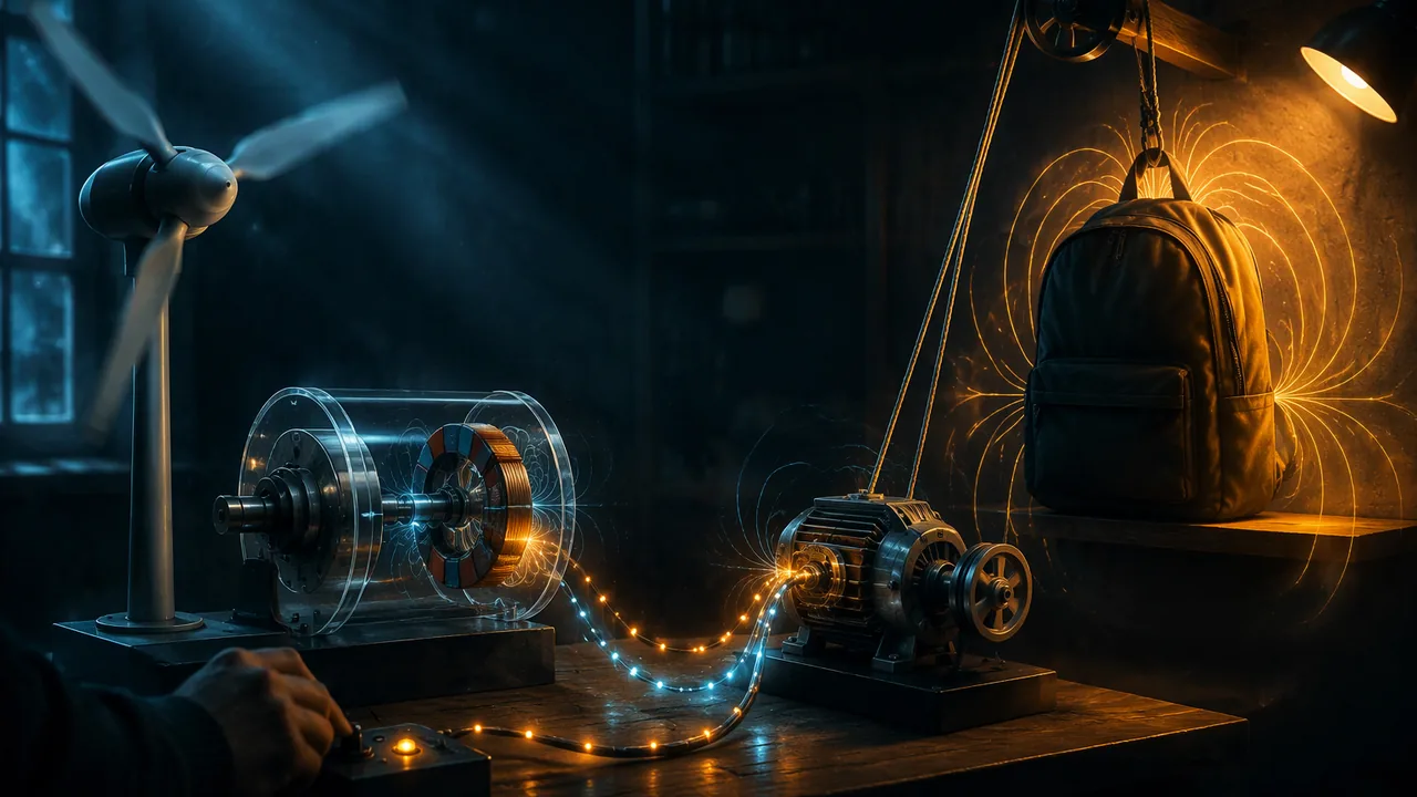
- Gravity. Lifting a 2.0 kg backpack 1.5 m onto a shelf takes mgh = 2.0 × 9.8 × 1.5 = 29.4 J. That energy is stored in the gravitational field of the Earth-backpack system. If the pack falls, the field does work on it and the stored energy becomes kinetic energy.
- Electric. Pulling a negative charge away from a positive one takes work against their attraction; the energy is stored in the electric field. Pushing two like charges closer together stores energy too, because they repel. Released, they fly apart.
- Magnetic. Separating opposite poles or pushing like poles together stores energy in the magnetic field.
The rule in every case: when objects that attract are pulled apart, or objects that repel are pushed together, energy is stored in the field. When they move the way the force pushes them, the field gives energy back as kinetic energy (and eventually thermal energy and sound). Drawing field lines helps: they point the way a force would push, and they crowd together where the field is strong.
The generator. In Atchison County, Missouri, wind pushes on turbine blades, which turn a shaft connected (usually through a gearbox) to a generator. In the generator, magnets and coils rotate relative to each other. Each time a coil turns, the magnetic field through it changes, which induces a current, the effect you measured in Lesson 2.2. But the induced current in the coil also creates its own magnetic field, and that field pushes back against the rotation. So the wind must keep doing work on the blades to keep them turning, and that work becomes the electrical energy sent to the grid. Energy flow: kinetic energy of air → kinetic energy of blades and rotor → (through the magnetic field) electrical energy → grid, with some energy lost as thermal energy and sound at every step.
The motor. Reverse the flow. A current sent through coils creates a magnetic field that pushes on permanent magnets, turning a shaft. Electrical energy → (through the field) kinetic energy of the shaft. An electric car’s motor does this, and many can run as generators when the car brakes, returning energy to the battery.
Why the field model matters. Without it, the energy seems to vanish and reappear. With it, you can account for every joule: it is stored in the arrangement of interacting objects, transferred through the field, and conserved overall. That is the systems thinking (CCC.4) that Unit 3 builds on.
📖 Read for this lesson
The reading opens over the lesson; close it to come back to exactly where you were. The checks below draw on it.
Formative check
Work through these before moving on. They are not graded — they tell you whether the standard below has landed yet.
Simulation & tools
Build a generator
Open the Generator screen. (1) Turn on the water faucet at a low flow and record the light bulb’s brightness and the turbine’s speed. (2) Increase the flow and record both again. (3) Increase the number of loops in the pickup coil and record the brightness at the same flow. (4) Replace the bulb with the voltmeter and describe how the reading changes as the magnet turns. Write an energy-flow diagram from the water to the bulb. No device? Draw the energy-flow diagram for a hand-crank flashlight and predict the effect of cranking faster.
Open in a new tab ↗ · PhET Interactive Simulations, University of Colorado Boulder · CC BY 4.0
Energy is stored in a magnetic field when you
Lifting a 2.0 kg backpack 1.5 m stores J in the Earth-backpack gravitational field (g = 9.8 m/s2).
A generator’s coil pushes back against the rotation when current flows, so the turbine must keep doing work to keep producing electricity.
How confident are you that you can use a field model to explain energy storage and transfer in interacting objects, motors and generators?
Practice
Work these on paper or in your notebook, then open Check your answer. Aim for all of Fluency and Application; try at least one Challenge.
Printable version: this unit’s practice workbook (PDF)
Fluency
Build speed and accuracy with the core skill.
- Find the gravitational potential energy gained when a 2 kg object is lifted 40 m (g = 9.8 m/s2).
Check your answer
Answer: 784.0 JPE = mgh. - Find the gravitational potential energy gained when a 70 kg object is lifted 40 m (g = 9.8 m/s2).
Check your answer
Answer: 27,440 JPE = mgh. - Find the gravitational potential energy gained when a 0.5 kg object is lifted 3 m (g = 9.8 m/s2).
Check your answer
Answer: 14.7 JPE = mgh. - When you pull two attracting magnets apart, is energy stored in the field or released from it?
Check your answer
Answer: Stored - When two like charges are pushed closer together, does the field’s stored energy increase or decrease?
Check your answer
Answer: IncreaseWork is done against the repulsion. - Write the energy chain for a generator in a wind turbine.
Check your answer
Answer: Kinetic energy of air → kinetic energy of blades and rotor → electrical energy (through the magnetic field), with some thermal energy and sound
Application
Use the skill in context. Show your reasoning.
- A 0.50 kg book is lifted 0.80 m and then dropped. How much energy is stored in the Earth-book field at the top, and how fast is the book moving just before it lands (ignore air resistance)?
Check your answer
Answer: 3.9 J; about 4.0 m/smgh = 0.50 × 9.8 × 0.80 = 3.92 J. ½(0.50)v2 = 3.92, so v = √(2 × 9.8 × 0.80) = 3.96 m/s. - A hand-crank flashlight is easy to crank with the bulb disconnected and harder to crank with it connected. Explain using the generator model.
Check your answer
Answer: With the bulb connected, current flows in the coils; that current’s magnetic field pushes back against the rotation, so you must do more work, and that work becomes the light and thermal energy of the bulb. - Draw (describe) field lines between two north poles facing each other and between a north and a south pole. In which case does pushing the magnets together store energy?
Check your answer
Answer: Between like poles the lines bend away from each other; between opposite poles they run from N to S. Pushing like poles together stores energy (work is done against repulsion).
Challenge
Stretch problems. Expect to think before you write.
- An electric car’s motor can run as a generator while braking. Trace the energy transfers during braking and explain why this extends the car’s range.
Check your answer
Answer: Kinetic energy of the car → rotation of the motor-generator → (through the magnetic field) electrical energy → chemical energy stored in the battery. Energy that friction brakes would have turned into thermal energy is partly recovered and used again for driving.
Review
Keep earlier skills sharp.
- A cyclist moving at 5 m/s brakes with a deceleration of 2 m/s2. How long does it take to stop, and how far does it travel while stopping?
Check your answer
Answer: 2.5 s; 6.2 mt = v0/a; d = v02/(2a). - A 1.0 kg cart at 4.0 m/s sticks to a 1.0 kg cart at rest. What is their speed after?
Check your answer
Answer: 2.0 m/s4.0 kg·m/s ÷ 2.0 kg.
Where the Energy Waits: Measuring the Field’s Store With a Spring Scale, and the Generator’s Push-Back With a Crank
Two recorded measurements constructed for this course and illustrative: (1) force against separation for two ceramic disk magnets, read from a 5 N spring scale; (2) hand-crank generator voltage and crank effort with and without a lamp load; U.S. Department of Energy, How Do Wind Turbines Work? and How a Wind Turbine Works (text version), retrieved November 5, 2026 · SLS original (constructed teaching data), with quoted public-domain U.S. Department of Energy text
Why this reading. The lesson’s model says two things that a student should not have to take on faith: that energy is stored when interacting objects are moved against their force, and that a generator’s coil pushes back when current flows. Both can be measured with a spring scale. This reading records both measurements, so that the field diagrams you draw have numbers under them and the true-false question about push-back has evidence behind it. It ends with the Department of Energy’s own description of the machines turning in Atchison County, Missouri, quoted, so your energy chain matches what is inside the nacelle. Both data sets are constructed teaching data and are labeled illustrative.
1. Energy stored in a magnetic field, measured
Set-up. Two ceramic disk magnets, 2.5 cm across, one taped to a table, the other hooked to a 5 N spring scale. The free magnet was pulled directly away from the fixed one and the scale read at each half-centimeter of separation (face to face).
| Separation (cm) | Attractive force (N) |
|---|---|
| 0.0 | 4.2 |
| 0.5 | 2.9 |
| 1.0 | 2.0 |
| 1.5 | 1.4 |
| 2.0 | 1.0 |
| 2.5 | 0.7 |
| 3.0 | 0.5 |
From force to energy. Work is force times distance, and the force changes as you pull, so add it up in steps: for each half-centimeter, average the force at its two ends and multiply by 0.005 m. Step 1: (4.2 + 2.9)/2 × 0.005 = 0.0178 J. Step 2: (2.9 + 2.0)/2 × 0.005 = 0.0123 J. Continue and the six steps sum to 0.052 J. That is the energy stored in the magnetic field of the pair by pulling them 3 cm apart. Let go and the free magnet accelerates back; it arrives with about that much kinetic energy, minus a little to air and friction, and the click you hear is the remainder leaving as sound and thermal energy. Compare it with the gravity case in the lesson: lifting a 2.0 kg backpack 1.5 m stores 2.0 × 9.8 × 1.5 = 29.4 J, about 400 times more, because the backpack is heavy and the lift is long. The bookkeeping is identical.
What the table also shows. The force falls fast with distance: it halves between 0 and about 1 cm and again by about 2 cm. Field lines drawn between the magnets would crowd tightly at the faces and spread out quickly beyond them. The stored energy is mostly banked in the first centimeter of pulling, where the force is largest; the last centimeter adds only (0.7 + 0.5)/2 × 0.005 = 0.003 J.
2. The generator’s push-back, measured
Set-up. A small hand-crank generator (a hobby DC motor run backward, like the one inside a crank flashlight) with a 10 cm crank handle, a digital multimeter across its terminals, and a spring scale hooked to the handle to read the tangential effort while cranking at a steady rate, timed with a metronome. Each row: open circuit (nothing connected but the meter), then a 6 V flashlight lamp connected.
| Crank rate (turns per second) | Voltage (V) | Effort, nothing connected (N) | Effort, lamp connected (N) | Extra effort due to the lamp (N) |
|---|---|---|---|---|
| 1.0 | 1.9 | 0.3 | 0.3 | 0.0 |
| 2.0 | 3.8 | 0.3 | 0.7 | 0.4 |
| 3.0 | 5.7 | 0.3 | 1.1 | 0.8 |
| 4.0 | 7.6 | 0.3 | 1.5 | 1.2 |
Reading the table. Two proportions. The voltage is proportional to the crank rate: faster rotation means the field through the coils changes faster, which is Lesson 2.2’s rule that a faster-moving magnet gives a bigger reading. And the extra effort with the lamp connected is also proportional to the crank rate. With nothing connected, the same 0.3 N of friction is all you feel at any speed and the lamp is dark. Connect the lamp and the handle fights back, harder the faster you go and the brighter the lamp burns. That extra force is the induced current’s own magnetic field opposing the rotation. Your hand does work against it, and that work is exactly the energy the lamp turns into light and heat. Disconnect the lamp and the push-back vanishes, because no current flows. This is the evidence for the true-false statement: a generator’s coil pushes back when current flows, so the turbine must keep doing work to keep producing electricity.
The energy check. At 3.0 turns per second the extra effort is 1.1 N at a 10 cm radius, so each turn does 1.1 N × 2π × 0.10 m = 0.69 J of extra work, and three turns a second is about 2.1 W of mechanical power going in. A small 6 V lamp drawing about 0.3 A at 5.7 V takes about 1.7 W. The rest, about 0.4 W, warms the coils and the gears. Energy in, energy out, losses named: that is the energy-flow diagram the lesson asks for, with numbers.
3. What the Department of Energy says is inside the turbine
The U.S. Department of Energy’s wind office describes the machine this way: “A wind turbine turns wind energy into electricity using the aerodynamic force from the rotor blades, which work like an airplane wing or helicopter rotor blade. When wind flows across the blade, the air pressure on one side of the blade decreases. The difference in air pressure across the two sides of the blade creates both lift and drag. The force of the lift is stronger than the drag and this causes the rotor to spin. The rotor connects to the generator, either directly (if it’s a direct drive turbine) or through a shaft and a series of gears (a gearbox) that speed up the rotation and allow for a physically smaller generator.” Its component guide adds the speeds: “… the low-speed shaft is connected to the rotor and spins between 8–20 rotations per minute,” and in the generator, “Copper windings turn through a magnetic field in the generator to produce electricity.”
Put your crank table on top of that description. The blades are your hand; the gearbox is what lets a rotor turning 8 to 20 times a minute spin the generator fast enough to matter; the copper windings turning through a magnetic field are your Part B coil with the “left in” moment removed; and the push-back you felt in the lamp column is why the wind must keep pushing on the blades for as long as the grid draws current. Energy flow: kinetic energy of air → kinetic energy of the rotor → (through the magnetic field) electrical energy in the windings → the grid, with thermal energy left in the gearbox, the windings and the air, and some sound.
The PhET generator screen, predicted
From the tables above: more water flow means faster rotation, a higher voltage and a brighter bulb; more loops in the pickup coil means a larger voltage at the same flow (each loop adds its own induced voltage, as each turn added field in Lesson 2.2); and the voltmeter swings back and forth through zero as the magnet turns, because the field through the coil grows, shrinks and reverses every revolution. A hand-crank flashlight is the same machine with your hand as the water.
Your turn
- Draw the field-line diagrams for the two magnets at 0.5 cm and at 3.0 cm apart, and use Table 1 to say which drawing should have more crowded lines and how much more energy is stored in the arrangement.
- Redo the step-by-step energy sum for Table 1 and confirm 0.052 J. Then estimate the free magnet’s speed on arrival if its mass is 20 g and all the stored energy became kinetic energy (½mv2).
- Write the energy-flow chain for the crank generator with the lamp, with the numbers from the 3.0 turns-per-second row, and mark where energy leaves the useful path.
Sources: U.S. Department of Energy, How Do Wind Turbines Work? (energy.gov); U.S. Department of Energy, How a Wind Turbine Works (text version) (energy.gov)