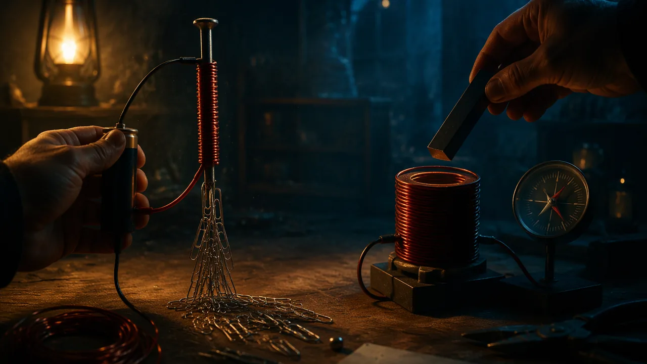
show that an electric current produces a magnetic field by building an electromagnet and measuring its strength, and show that a changing magnetic field produces a current in a coil.
Instruction
Two discoveries. In 1820, Hans Christian Ørsted noticed that a compass needle swung when he switched on a current in a nearby wire: an electric current produces a magnetic field. About ten years later, Michael Faraday showed the reverse: moving a magnet near a coil of wire produces a current in the coil, but only while the magnet is moving. Together these discoveries are the basis of every electric motor and every generator, including the ones in the wind turbines of Atchison County, Missouri. 9-12.PS2.B.2 asks you to produce evidence for both.
Part A: current makes a magnetic field. Lay an insulated wire across the top of a compass (or a phone running a compass app, lying flat under the wire), lined up north-south. Touch the wire’s ends to a D-cell for a few seconds: the needle swings. Reverse the battery and it swings the other way. The current creates a magnetic field that circles the wire. Wind the wire into a coil and each loop’s field adds to the next; wrap the coil around an iron nail and the iron’s own magnetic domains line up with the field, making it far stronger. That is an electromagnet.
Measuring strength. Count how many small paper clips the nail’s tip can lift in a chain or cluster. More coils should mean a stronger field. Keep the battery, the nail and the wire the same; change only the number of turns (10, 20, 30, 40). Make every coil the same way, tightly wound in one direction, and connect only for about 10 seconds per test, because the wire and battery warm up and the battery runs down. A fresh battery at the start and a check at the end tell you whether that happened.
What to expect. Illustrative results: 10 turns lifted 2 clips, 20 turns 5, 30 turns 7, 40 turns 10. The graph of clips against turns rises roughly in a straight line: field strength increases with the number of turns. Counting clips is a coarse measurement (a clip is all or nothing), so repeat each test three times and average.
Part B: changing magnetic field makes a current. Wind about 100 turns of thin insulated wire around a cardboard tube and connect the ends to a digital multimeter set to its most sensitive current (μA or mA) or voltage (mV) range. No multimeter at home? Make a compass detector: run the coil’s two leads about 1 m away from the tube, wind 20 turns of them around a compass, and watch the needle swing instead. No battery is used. Push a strong magnet into the tube: the reading jumps. Hold it still inside: the reading returns to zero. Pull it out: the reading jumps the other way. Move it faster: a bigger reading. The current appears only when the magnetic field through the coil is changing. That is electromagnetic induction.
Why it matters. In a generator, a turbine spins a magnet near coils (or coils near a magnet), so the field through the coils changes continuously and current flows continuously. In a motor, current in coils produces a magnetic field that pushes against a permanent magnet and makes the shaft turn. The same physics, run in two directions.
Safety. Do this lab at home with an adult nearby. Wear safety glasses or goggles: wire ends are sharp and can spring back. Never connect wire directly across a battery for more than about 10 seconds; it gets hot. Use only D-cells, never a wall outlet. Strong magnets can pinch fingers and snap together; keep them away from phones, bank cards, pacemakers and young children, who can be badly hurt if they swallow small magnets.
📖 Read for this lesson
The reading opens over the lesson; close it to come back to exactly where you were. The checks below draw on it.
Lab: Building an Electromagnet and Inducing a Current
Question. How does the number of coils change the strength of an electromagnet, and what must happen to a magnet near a coil for a current to flow?
Materials
- Two D-cell batteries in a holder (or taped end to end), and 2 m of insulated copper wire (bell wire or magnet wire from a hardware store) with stripped ends
- A large iron nail (about 10 cm), a box of small steel paper clips, and a magnetic compass (or a phone with a compass or magnetometer app)
- A cardboard tube (a paper-towel roll) wound with about 100 turns of thin insulated wire, and a digital multimeter if you have one; without one, use the compass detector in step 4
- A strong bar or neodymium magnet that fits in the tube
- Safety glasses or goggles, masking tape
- Work at home with an adult nearby. Wear safety glasses or goggles; stripped wire ends are sharp and can spring back.
- Connect the circuit for no more than about 10 seconds at a time; the wire and battery get warm. Use only D-cells, never a wall outlet.
- Strong magnets can pinch skin and snap together; handle them one at a time and keep them away from phones, cards, anyone with a pacemaker, and young children, who must never be able to swallow one.
Procedure
- Lay a straight section of wire over the compass (or over a phone running a compass app), aligned north-south. Connect the battery for 3 seconds and record the needle’s movement. Reverse the battery connections and repeat.
- Wrap 10 tight turns of wire around the nail, all in the same direction. Connect the battery, dip the nail tip into the paper clips, lift, count the clips, then disconnect. Repeat three times.
- Add turns to make 20, 30 and 40, repeating the three trials for each. Record the average number of clips.
- Connect the 100-turn coil to the multimeter on its most sensitive range. No multimeter? Run the coil’s leads about 1 m away from the tube, wind 20 turns of them around the compass, and use the needle’s swing (direction and size) as your reading. Push the magnet into the tube, hold it still, then pull it out. Record the reading during each motion.
- Repeat step 4 moving the magnet slowly and then quickly, and with the magnet turned around. Record the readings.
- Graph average clips lifted against number of turns.
Data
| Turns | Clips trial 1 | Clips trial 2 | Clips trial 3 | Average |
|---|---|---|---|---|
| 10 | ||||
| 20 | ||||
| 30 | ||||
| 40 |
| Magnet motion (induction) | Meter reading (sign and size) |
|---|---|
| Pushed in slowly | |
| Held still inside | |
| Pulled out slowly | |
| Pushed in quickly | |
| Magnet reversed, pushed in |
Analysis
- Claim: an electric current produces a magnetic field. Evidence: the compass and electromagnet results. Reasoning: explain why reversing the battery reversed the needle and why more turns lifted more clips.
- Claim: a changing magnetic field produces a current. Evidence: your induction readings. Reasoning: explain why the reading was zero when the magnet was still and larger when it moved faster.
- Identify two sources of error in the clip test (for example, battery running down, uneven winding) and how each would affect your graph.
- Explain how a wind turbine could keep a current flowing continuously, using what you observed in Part B.
If you cannot do this lab in person: Missing a material, or a step will not work? Use the PhET Faraday’s Electromagnetic Lab (Electromagnet and Pickup Coil screens) to vary the number of loops and the magnet’s motion, and complete the same analysis with the recorded data set in this lesson’s reading, a full trial-by-trial run of both parts.
Formative check
Work through these before moving on. They are not graded — they tell you whether the standard below has landed yet.
A magnet sits motionless inside a coil connected to a meter. The reading is
Which change would NOT make the electromagnet stronger?
Reversing the direction of the current in a wire reverses the direction of its magnetic field.
Write two claim-evidence-reasoning paragraphs: one showing that a current produces a magnetic field and one showing that a changing magnetic field produces a current. Use numbers from your data.
How confident are you that you can produce evidence that a current makes a magnetic field and a changing magnetic field makes a current?
Practice
Work these on paper or in your notebook, then open Check your answer. Aim for all of Fluency and Application; try at least one Challenge.
Printable version: this unit’s practice workbook (PDF)
Fluency
Build speed and accuracy with the core skill.
- What happens to a compass needle near a wire when current flows? When the current is reversed?
Check your answer
Answer: It swings; it swings the other way. - Name three ways to make an electromagnet stronger.
Check your answer
Answer: More turns of wire, an iron core, a larger current. - A magnet is pushed into a coil connected to a meter, then held still, then pulled out. Describe the three readings.
Check your answer
Answer: A reading one way while pushing in; zero while still; a reading the other way while pulling out. - In the clip test, name the independent variable, the dependent variable and two controlled variables.
Check your answer
Answer: Independent: number of turns. Dependent: clips lifted. Controlled: battery, nail, wire, connection time. - Why does the induction part of the lab use no battery?
Check your answer
Answer: To show that the moving magnet alone produces the current.
Application
Use the skill in context. Show your reasoning.
- Illustrative data: 10 turns lifted 2 clips, 20 turns 5, 30 turns 7, 40 turns 10. The best-fit line is clips = 0.26 × turns − 0.5. Predict the clips for 50 turns and say one reason the real result might be lower.
Check your answer
Answer: About 12 clips. The battery may be running down, the wire heating, or the nail becoming saturated, so the trend may level off.0.26 × 50 − 0.5 = 12.5, about 12. - A student reads 0.4 mA when pushing the magnet in slowly and 1.3 mA when pushing it in quickly. Explain the difference.
Check your answer
Answer: Moving faster changes the magnetic field through the coil more quickly, which induces a larger current. - An electromagnet in a scrapyard crane lifts cars and then drops them when the operator switches it off. Explain why a permanent magnet could not do this job as well.
Check your answer
Answer: The electromagnet’s field exists only while current flows, so switching off the current releases the load. A permanent magnet’s field cannot be switched off.
Challenge
Stretch problems. Expect to think before you write.
- A student holds a magnet still and moves the coil over it instead. Will a current be induced? Explain what the necessary condition really is.
Check your answer
Answer: Yes. What matters is that the magnetic field through the coil changes; relative motion of coil and magnet does this whichever one moves.
Review
Keep earlier skills sharp.
- An object starts at 2 m/s and accelerates at 1 m/s2 for 9 s. How far does it travel?
Check your answer
Answer: 58.5 md = v0t + ½at2. - Convert 1250 mL to L.
Check your answer
Answer: 1.25 L
Clips, Compass and Meter: A Recorded Run of the Electromagnet Lab, and Faraday’s Own Account of the Moving Magnet
One recorded run of the Lesson 2.2 procedure (D-cell electromagnet on a 10 cm iron nail, 10 to 40 turns, three trials each; 100-turn pickup coil on a digital multimeter, DC millivolt range), constructed for this course and illustrative; Michael Faraday, Experimental Researches in Electricity, vol. 1, First Series, read to the Royal Society 24 November 1831, paragraph 39, Project Gutenberg ebook 14986, retrieved November 5, 2026 · SLS original (constructed teaching data), with a public-domain primary source (Faraday, 1831)
Why this reading. The lab’s alternative route points to “the recorded data set in this lesson’s reading,” and the open question says to “use numbers from your data.” If you have no nail, no wire or no meter at home, or a step will not work, here is a full recorded run of the procedure, trial by trial, with the meter readings for every motion in Part B. It is constructed teaching data and is labeled illustrative. Beneath it is something that is not illustrative at all: the paragraph in which Michael Faraday first reported, in 1831, exactly the experiment you do in Part B, so you can compare his sentences with your table.
Part A. Current makes a magnetic field
Set-up. Two fresh D-cells in a holder (3.1 V measured at the start), 2 m of enamelled copper wire, a 10 cm iron nail, small steel paper clips (about 0.4 g each), a compass. Each test connected for no more than 10 s.
The straight wire over the compass. Wire laid north-south over the needle; battery connected for 3 s: the needle swung about 35° toward the east and returned when disconnected. Battery reversed: the needle swung about 35° toward the west. Wire lifted 5 cm above the compass: swing about 10°. Three observations, one claim: a current makes a magnetic field, its direction depends on the direction of the current, and it weakens with distance.
The electromagnet. Clips lifted from a heap by the nail’s tip, counted after lifting clear; three trials per coil.
| Turns | Clips, trial 1 | Clips, trial 2 | Clips, trial 3 | Average |
|---|---|---|---|---|
| 10 | 2 | 2 | 2 | 2.0 |
| 20 | 5 | 4 | 6 | 5.0 |
| 30 | 7 | 8 | 6 | 7.0 |
| 40 | 10 | 9 | 11 | 10.0 |
Battery voltage measured at the end of the twelve tests: 2.9 V, down from 3.1 V.
Reading the table. The averages (2.0, 5.0, 7.0, 10.0) rise close to a straight line, about one clip per four turns. Each turn adds its own loop of field around the nail, and the fields add. The graph does not pass exactly through the origin, and the last point is a little low; the 0.2 V drop in the battery over the run is one candidate (less current, weaker field for the same turns) and the coarseness of the count is the other (a clip either lifts or it does not, so the true strength between 9 and 10 clips is invisible). Both are the “two sources of error” the analysis asks for, and both push the 40-turn point down, not up. Uneven winding would scatter points in either direction.
Part B. A changing magnetic field makes a current
Set-up. About 100 turns of thin insulated wire on a cardboard tube, connected to a digital multimeter on its 200 mV DC range. No battery in the circuit. Neodymium bar magnet, 2 cm long. The meter reads the peak value it showed during each motion.
| Motion of the magnet | Meter reading (sign and size) |
|---|---|
| Pushed in slowly (about 1 s) | +3 mV |
| Held still inside (5 s) | 0 mV |
| Pulled out slowly (about 1 s) | −3 mV |
| Pushed in quickly (about 0.2 s) | +14 mV |
| Pulled out quickly | −15 mV |
| Magnet reversed (other pole first), pushed in quickly | −14 mV |
| Coil moved over a stationary magnet, quickly | +13 mV |
With a compass detector instead of a meter. If you used the compass detector from step 4, your readings are needle swings, not millivolts. The patterns are the same: a swing one way pushing in, no swing while the magnet is still, a swing the other way pulling out, and a bigger swing for a faster push. Record the direction and estimate the size in degrees.
Reading the table. Four patterns, each a piece of evidence. (1) Still magnet, zero reading, no matter how strong the magnet: a magnetic field alone does not make a current. (2) In and out give opposite signs: the direction of the induced current depends on whether the field through the coil is growing or shrinking. (3) Fast motion, five times the reading of slow motion: the current depends on how quickly the field changes. (4) Reversing the magnet reverses the sign, and moving the coil instead of the magnet gives the same result: only the relative motion matters. Pattern 4 is why a generator can be built either way, spinning magnets past fixed coils or coils past fixed magnets.
Faraday’s account, 1831
Faraday reported these effects to the Royal Society on November 24, 1831. His “helix” is your coil, his “galvanometer” is your meter, and the needle’s deflection is your millivolt reading. Paragraph 39 of the First Series, exactly as printed:
“All the similar ends of the compound hollow helix (34.) were bound together by copper wire, forming two general terminations, and these were connected with the galvanometer. The soft iron cylinder (34.) was removed, and a cylindrical magnet, three quarters of an inch in diameter and eight inches and a half in length, used instead. One end of this magnet was introduced into the axis of the helix (fig. 4.), and then, the galvanometer-needle being stationary, the magnet was suddenly thrust in; immediately the needle was deflected in the same direction as if the magnet had been formed by either of the two preceding processes (34. 36.). Being left in, the needle resumed its first position, and then the magnet being withdrawn the needle was deflected in the opposite direction.”
Set his sentences beside your table. “Suddenly thrust in”: a deflection (your +14 mV). “Being left in, the needle resumed its first position”: zero while still. “Being withdrawn … deflected in the opposite direction”: your −15 mV. Three of your four patterns are in one paragraph written 195 years ago; the fourth, that speed matters, he reports in the paragraphs that follow. Notice also what he does that you should do: he gives the magnet’s dimensions, the number of the earlier paragraph describing the helix, and the figure number. A reader could rebuild his apparatus. Your lab write-up should let a reader rebuild yours.
From the table to the turbine
The analysis asks how a wind turbine could keep a current flowing continuously. Your Part B table says the answer in numbers: a current appears only while the field through the coil is changing, and it is larger when the change is faster. Rotate a magnet next to a coil and the field through the coil grows, shrinks, reverses and grows again with every turn; the reading would swing +, 0, −, 0, + without stopping. A turbine is a machine for never letting the magnet be “left in.”
Your turn
- Graph the average clips against turns, draw a best-fit line, and state its slope in clips per turn. Say whether the 40-turn point lies above or below the line and give the more likely reason.
- Write the two claim-evidence-reasoning paragraphs the lesson asks for, using at least two numbers from Part A and two from Part B.
- Faraday’s magnet was 8.5 inches long and yours 2 cm. Predict, with a reason, which would give the larger reading pushed into the same coil at the same speed, and what you would need to know to be sure.
Sources: Michael Faraday, Experimental Researches in Electricity, Volume 1 (Project Gutenberg ebook 14986) (gutenberg.org)