analyze patent drawings as a visual language with its own conventions, and break down the engineering design process behind a biomedical invention.
Instruction
A patent drawing is one of the strictest forms of visual communication there is. It must show an invention so clearly that a skilled person could understand how to make it, using only black lines on white paper. Within those limits, patent drawings can be beautiful, and they have a history as rich as any art form.
From models to drawings. In the nineteenth century the U.S. Patent Office generally required inventors to submit a small working model with their application. The requirement was dropped in 1880, and drawings became the main visual record of an invention. U.S. patents are public-domain government documents, so you can study, copy and annotate their drawings freely.
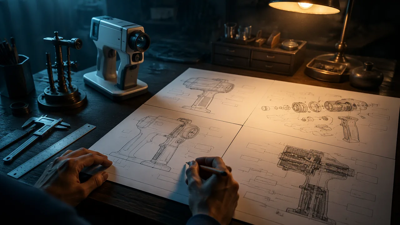
The conventions. The USPTO’s drawing rules (37 CFR 1.84) require, among other things, black-and-white drawings with clean, durable lines; each view labeled as a figure (“FIG. 1”, “FIG. 2”); reference numerals that point to each part with thin lead lines and match the numbers used in the written description; and reference characters at least about 0.32 cm (1/8 inch) high. Shading is done with lines, not gray tones, to show surfaces and curvature. The views you will use are the same ones engineers and illustrators use: orthographic views (front, top, side, each drawn flat and square-on), perspective or isometric views that show three dimensions, exploded views that separate parts along their assembly lines, and sectional views that cut through the object to show inside.
Inventors to study. Patricia Bath, an ophthalmologist, invented a device and method that used a laser to remove cataracts, patented in 1988; she is recognized as the first African American woman physician to receive a patent for a medical invention. Her work grew from her concern about blindness in underserved communities. Marie Van Brittan Brown, a nurse in New York, with her husband Albert Brown, patented a home security system in 1969 that used a camera, a monitor and remote door control, an early ancestor of today’s video doorbells. Wilson Greatbatch, an engineer, developed an implantable cardiac pacemaker around 1960, famously after installing the wrong resistor in a circuit and noticing it produced a heartbeat-like pulse. A Missouri example: the glass scientist Delbert E. Day, now a Curators’ Distinguished Professor emeritus at Missouri University of Science and Technology in Rolla, and Gary J. Ehrhardt patented glass microspheres for radiation therapy (US 4,789,501, issued 1988 and assigned to the Curators of the University of Missouri): beads smaller than about 75 micrometers that carry a radioactive element evenly through the glass so they can deliver radiation close to a tumor. Its five figures are not pictures of a device but a composition diagram and graphs, a reminder that a patent drawing can be evidence as well as an illustration.
The engineering design process. These inventions followed a recognizable process, though never in a straight line. Define the problem, including who has it, the criteria (what success looks like) and the constraints (limits such as cost, size, safety and materials). Research existing solutions, including patents. Generate many concepts. Select one using the criteria. Prototype it. Test it against the criteria. Iterate: improve and test again. Communicate the design, which includes drawings and, sometimes, a patent. Designers loop back constantly: a failed test sends you back to concepts; new research changes the problem definition.
Your study. Choose one biomedical technology, such as the pacemaker, the Missouri glass microspheres, the insulin pump, the cochlear implant, the pulse oximeter or the powered prosthetic hand, and map its development onto the process, marking where it looped back. Use sources you can cite.
📖 Read for this lesson
The reading opens over the lesson; close it to come back to exactly where you were. The checks below draw on it.
Formative check
Work through these before moving on. They are not graded — they tell you whether the standard below has landed yet.
In a patent drawing, what connects the number 14 on FIG. 2 to the text?
The engineering design process runs in a straight line from problem to finished product without going back.
Patricia Bath
Tap to revealLaser cataract device and method, patented 1988
Marie Van Brittan Brown
Tap to revealHome security system with camera and monitor, patented 1969 with Albert Brown
Wilson Greatbatch
Tap to revealImplantable pacemaker, developed around 1960
Patent models
Tap to revealGenerally required by the U.S. Patent Office until 1880
Delbert E. Day (Missouri S&T, Rolla)
Tap to revealGlass microspheres for radiation therapy, US 4,789,501, with Gary J. Ehrhardt, issued 1988
Map your chosen biomedical technology onto the engineering design process. Name one moment where the designers looped back, and cite the source that tells you so.
How confident are you that you can analyze patent drawings as a visual language and map a biomedical invention onto the engineering design process?
Practice
Work these on paper or in your notebook, then open Check your answer. Aim for all of Fluency and Application; try at least one Challenge.
Printable version: this unit’s practice workbook (PDF)
Fluency
Build speed and accuracy with the core skill.
- Match each inventor to the invention and year the lesson gives: Patricia Bath; Marie Van Brittan Brown (with Albert Brown); Wilson Greatbatch; Delbert E. Day (with Gary J. Ehrhardt).
Check your answer
Answer: Bath: a laser device and method to remove cataracts, patented 1988. Brown: a home security system with camera, monitor and remote door control, patented 1969. Greatbatch: an implantable cardiac pacemaker, developed around 1960. Day and Ehrhardt: glass microspheres for radiation therapy, US 4,789,501, issued 1988.Day is a Curators’ Distinguished Professor emeritus at Missouri University of Science and Technology in Rolla; the patent is assigned to the Curators of the University of Missouri. - List the eight stages of the engineering design process in the order the lesson gives them.
Check your answer
Answer: Define the problem; research existing solutions; generate concepts; select one; prototype; test; iterate; communicate.The process is never a straight line: designers loop back after failed tests and new research. - Name four drawing conventions required by the USPTO rules (37 CFR 1.84) as the lesson describes them.
Check your answer
Answer: Black-and-white drawings with clean, durable lines; each view labeled as a figure (FIG. 1, FIG. 2); reference numerals with thin lead lines that match the written description; reference characters at least about 0.32 cm (1/8 inch) high. Shading is done with lines, not gray tones.Any four of these five are correct.
Application
Use the skill in context. Show your reasoning.
- Explain what changed in 1880 for U.S. patents and why it matters to anyone studying patent drawings today.
Check your answer
Answer: The Patent Office dropped its general requirement for a small working model, so drawings became the main visual record of an invention. Because U.S. patents are public-domain government documents, their drawings can be studied, copied and annotated freely.This makes the patent archive a large open collection of technical illustration. - The Day-Ehrhardt microspheres are smaller than about 75 micrometers. How many millimeters is that? About how many such beads, side by side, would span 1 mm?
Check your answer
Answer: 0.075 mm; about 13 beads.1 mm = 1,000 micrometers, so 75 / 1,000 = 0.075 mm. 1 / 0.075 = 13.3, so about 13 beads at the maximum size (more if smaller). - The Day-Ehrhardt patent’s five figures are a composition diagram and graphs, not pictures of a device. What does the lesson say this shows about patent drawings?
Check your answer
Answer: A patent drawing can be evidence as well as an illustration: figures can present data and composition that support the invention’s claims.Not every invention is a machine; this one is a composition of matter (glass beads carrying a radioactive element). - Map the pacemaker story onto the design process: at which stage did Greatbatch’s wrong resistor fit, and why is it an example of looping back?
Check your answer
Answer: It happened during prototyping and testing a circuit: installing the wrong resistor produced a heartbeat-like pulse. Noticing it sent him back to concepts and changed the direction of the design, which is a loop back rather than a straight line.A strong answer names the stage and explains how the unexpected test result redirected the work. Cite the lesson as the source.
Review
Keep earlier skills sharp.
- Review (Semester A, Unit 3): Patent drawings shade with lines, not gray tones. Which Semester A panel rule also asks designers to make images work without relying on color?
Check your answer
Answer: Use value (light and dark) as well as hue so the panel still works in grayscale, and test by converting it to grayscale.Both rules make an image readable when printed or copied in black and white.
Three Real Patents: Numbers, Drawings in Words, the Drawing Rules and a Pacemaker Design Loop
US 4,744,360 (Bath), US 3,482,037 (Brown), US 3,057,356 (Greatbatch), retrieved from Google Patents 2026-09-26; 37 CFR 1.84 from eCFR 2026-09-26; Lemelson Center, Innovative Lives: Making Hearts Beat: Wilson Greatbatch (Internet Archive copy, retrieved 2026-09-26) · Public domain (U.S. patents; 37 CFR); short quotation and paraphrase from the Smithsonian Lemelson Center, cited; SLS original (drawing descriptions and tables)
Why this reading. The lesson asks you to annotate two patent drawings, name their conventions and map a biomedical invention onto the engineering design process, citing the source that shows a loop back. Here are three real U.S. patents (public domain) with their numbers, dates and drawings described in words, the drawing rules you annotate against, and a verified account of one invention’s design loop. Nothing needs a search or a link.
Three real patents
| US 4,744,360 | US 3,482,037 | US 3,057,356 | |
|---|---|---|---|
| Title | Apparatus for ablating and removing cataract lenses | Home security system utilizing television surveillance | Medical cardiac pacemaker |
| Inventor(s) | Patricia E. Bath | Marie Van Brittan Brown and Albert L. Brown | Wilson Greatbatch |
| Filed | Dec. 18, 1986 (Ser. No. 06/943,098) | Aug. 1, 1966 (Ser. No. 569,319) | July 22, 1960 (Ser. No. 44,796) |
| Issued | May 17, 1988 | Dec. 2, 1969 | Oct. 9, 1962 |
| Claims | 7 | 1 | 4 |
| Figures | 2 (one drawing sheet) | 11 (three drawing sheets) | 3 (one drawing sheet) |
| Filing to issue | 516 days (about 1.4 years) | 1219 days (about 3.3 years) | 809 days (about 2.2 years) |
Source and rights. U.S. patent full text and drawings, retrieved from Google Patents on September 26, 2026 (the USPTO’s own full text carries the same numbers). U.S. patents are government documents in the public domain. The lesson’s flashcards give these inventors and years; the numbers above are checked against the patents.
The drawing rules to annotate against (37 CFR 1.84, retrieved from eCFR Sept. 26, 2026)
- Numbers, letters and reference characters must measure at least .32 cm (1/8 inch) in height, must be plain and legible, must not be enclosed in outlines such as circles, and should not cross lines or sit on shaded surfaces.
- Lead lines run between a reference character and the detail it names. They should be as short as possible, must not cross each other, and are required for each reference character except one placed on a surface it labels (which is underlined).
- Views must not be connected by projection lines and must not contain center lines. Exploded views, with the separated parts embraced by a bracket, are permitted.
- Every line, number and letter must be durable, clean, black, sufficiently dense and uniformly thick. Lines of different thickness may be used where the thickness has a meaning.
- Shading is encouraged if it aids understanding; light should come from the upper left corner at an angle of 45 degrees; solid black shading areas are not permitted except for bar graphs or color.
- Scale must be large enough to show the mechanism without crowding when the drawing is reduced to two-thirds. Notes such as “actual size” are not permitted.
- Margins: top at least 2.5 cm, left at least 2.5 cm, right at least 1.5 cm, bottom at least 1.0 cm.
Drawing 1: US 4,744,360, Bath (described)
One sheet, headed “U.S. Patent, May 17, 1988, 4,744,360.” FIG. 1 is a schematic side view. At left, an outline of an eye in section with the lens drawn as a small lens-shaped form, labeled 22. A thin curved line enters the eye and joins a straight tapered handpiece. From the handpiece’s right end, three lines with arrowheads lead to three labeled boxes stacked at right: IRRIGATOR (31) above, LASER (20) in the middle, ASPIRATOR (34) below. A numeral 24 with a short arrow stands above the eye. FIG. 2 is a cross-section, marked by a pair of arrows and the number 2 on FIG. 1, of the flexible line (26): a large circle filled with slanted solid and dashed hatching for the optical fiber (28), wrapped by a thin ring (30, the irrigation sleeve), with an aspirator sleeve (32) running around the lower half only, like a shallow cup. A dimension mark labeled d shows the width of a sleeve. Words on the drawing are hand-lettered in italics. The patent’s text says the flexible line can be no greater than 1 mm in diameter, the optical fiber no more than 600 microns, and the aspiration sleeve no more than 0.1 mm thick.
Drawing 2: US 3,057,356, Greatbatch (described)
One sheet headed “Oct. 9, 1962, W. Greatbatch, 3,057,356, Medical cardiac pacemaker, Filed July 22, 1960.” FIG. 1 is a circuit diagram (numeral 10): a transformer (19) with two coils (18, 20), a resistor (22), a capacitor (21), a transistor (14, with collector 15, base 16, emitter 17), a battery (23), and two leads (24, 25) running right to electrodes (13) drawn as a small two-pronged plug on a cable (12). FIG. 2 repeats the circuit with a second transistor (26), two more resistors (30, 31) and a capacitor (32) for higher power; primed numerals (14′, 19′) mark parts repeated from FIG. 1. FIG. 3 is a perspective view: a flat, thick disc (11) shaded with stipple dots, with its cable (12) leaving the edge, drawn broken by a dashed section, ending at the electrodes (13). The patent text says the pulse is about 10 volts and about one millisecond, one pulse per second in the described circuit, and that the disc is cast in a hard epoxy compound covered with a thin coating of silicone rubber. Dimensions printed in the OCR text of this patent are garbled, so read them from the original sheet, not from this description.
Drawing 3: US 3,482,037, Brown (figure list)
Eleven figures on three sheets: FIG. 1, a perspective view, partly broken away, of the system installed at an entrance door and in a bedroom; FIG. 2, a fragmentary perspective of the front of the door; FIG. 3, an enlarged sectional view taken on line 3-3 of FIG. 2; FIG. 4, a rear elevation of part of the door; FIG. 5, an enlarged rear view of the apparatus at the door; FIG. 6, a front view of the video-audio receiver and control unit; FIG. 7, a diagram of the system; FIGS. 8 to 11, a perspective, side, top and sectional view of a second scanning device. The text numbers the parts: cabinet 20, door 22, video scanner 26, lens barrel 28, microphone 55, loudspeaker 56, television antenna 58, solenoid-operated bolt lock 60. Claim 1 of this patent describes windows in the door covered by pivoting protective plates, a cabinet containing a video scanning device that a motor drives up and down past the windows, a video transmitter, and a radio receiver and transmitter to control the motor from inside the home.
Evidence of a design loop: the pacemaker
The problem, in the patent’s own words. The patent’s background says existing artificial pacemakers “have required considerable power” and could not run from a battery without frequent replacement, and that their size and power needs required external mounting with wires through the skin, which caused discomfort and the possibility of infection. Its stated objects include low power consumption, battery operation for long periods, and materials compatible with the body so that permanent implantation is practical. Those are criteria and constraints.
The loop. The Smithsonian’s Lemelson Center account of Greatbatch’s work reports that about 1956, while building a circuit to record heart sounds, he grabbed the wrong resistor and the circuit pulsed for 1.8 milliseconds, stopped for a second and repeated, a rhythm he recognized as heartlike. On May 7, 1958 a prototype took control of a dog’s heartbeat. He recalled: “We were pretty naive about early pacemaker designs. We thought that wrapping the module in electric tape would seal it.” Body fluid got through, and the first implant lasted only four hours. They switched to casting the unit in a block of epoxy, and within a year devices could last four months. The patent, filed in 1960, describes exactly that solution: the circuit cast into hard epoxy and coated with silicone rubber. Claim 1 of the patent requires a circuit “cast in a potting compound” and claim 2 adds silicone rubber, so the fix that followed the failure ended up in the legal boundary of the invention. That is a documented iteration: prototype, test, failure, redesign, retest.
The other inventor’s process. Bath’s background describes three earlier approaches to cataract removal: cutting and aspirating with a sharp instrument; an ultrasonic probe through an incision of typically 3 mm; and earlier laser methods. Her invention aims for an incision of 1 mm or less. Her patent’s example reports laser ablation tests on bovine lenses and human lenses from cadaver eyes at a 308 nm wavelength, with a threshold near 10 mJ/mm2 for bovine nucleus and rates of 13 and 23 microns per pulse at two energy levels; the patent calls 308 nm “the most effective experimental wavelength.”
A model process map (Greatbatch)
| Stage | Evidence | Source |
|---|---|---|
| Define the problem | Pacemakers need too much power and wires through the skin | US 3,057,356 background |
| Criteria and constraints | Low power; battery; body-compatible materials; implantable | US 3,057,356 objects |
| Ideas | A blocking-oscillator pulse circuit, from an accidental resistor swap | Lemelson Center |
| Prototype and test | May 7, 1958 dog test | Lemelson Center |
| Loop back | Tape seal failed in 4 hours; changed to epoxy block; 4 months | Lemelson Center |
| Communicate | Patent filed July 22, 1960; issued Oct. 9, 1962 | US 3,057,356 |
Not hosted. The lesson also says the U.S. Patent Office generally required models until 1880. That statement could not be checked against a primary source for this reading; treat it as the lesson’s claim.
Sources: US 4,744,360, Bath, Apparatus for ablating and removing cataract lenses (patents.google.com); US 3,482,037, Brown and Brown, Home security system utilizing television surveillance (patents.google.com); US 3,057,356, Greatbatch, Medical cardiac pacemaker (patents.google.com); 37 CFR 1.84, Standards for drawings (ecfr.gov); Smithsonian Lemelson Center, Innovative Lives: Making Hearts Beat: Wilson Greatbatch (invention.si.edu)
A Missouri Patent: US 4,789,501, Glass Microspheres for Radiation Therapy
US 4,789,501, Day and Ehrhardt, Glass microspheres (Google Patents record and patent text, retrieved 2026-11-10); Missouri S&T News, “S&T launches glass science lecture series honoring Delbert Day,” Oct. 23, 2026 (retrieved 2026-11-10); figure descriptions, claim breakdown and arithmetic are SLS original · Public domain (U.S. patent text); paraphrase from Missouri S&T News, cited; SLS original (descriptions and tables)
Why this reading. Lesson 3.1 studies the patent drawing as a visual language and the design process behind biomedical inventions. This reading adds a Missouri patent for a cancer-treatment technology: its numbers copied from the patent, what it protects, how its five figures differ from the device drawings in the other three patents, its first claim broken into elements, and evidence of a design loop. Patent text is public domain. This is a study of a patent, not medical information about any treatment.
The record (Google Patents, retrieved Nov. 10, 2026)
| Item | As recorded |
|---|---|
| Patent number | US 4,789,501 |
| Title | Glass microspheres |
| Inventors | Delbert E. Day; Gary J. Ehrhardt |
| Application | US 06/673,123, filed November 19, 1984 |
| Issued | December 6, 1988 |
| Assignment | Assigned to the Curators of the University of Missouri |
| Claims | 8 (claim 1 independent; claims 2 to 8 refer back to claim 1) |
| Figures | 5 |
| Status | Expired |
The Missouri connection. Missouri University of Science and Technology (Missouri S&T) in Rolla, part of the University of Missouri System, describes Delbert Day as a Curators’ Distinguished Professor emeritus of materials science and engineering and a prolific inventor whose specialty glasses have contributed to treatments for cancer, bone tissue regeneration and wound care. In October 2026 the university began a lecture series on glass science named for him (Missouri S&T News, Oct. 23, 2026).
What the patent protects
The abstract reads: “A radioactive microsphere for radiation therapy of a mammal comprising a biologically compatible glass material containing a beta or gamma emitting radioisotope distributed substantially uniformly throughout the glass.” In plain words: tiny glass beads, no more than about 75 micrometers across in claim 1, made so that a radioactive element is spread evenly through the glass. The background explains the medical idea the invention builds on: a small quantity of radioactive particles is injected so that the particles lodge in the capillary bed around a tumor and give a local field of radiation. It notes that yttrium was chosen because it emits nearly 100 percent beta radiation.
Evidence of a design loop
The background describes the earlier approach: yttrium oxide powder suspended in a thick liquid. The patent’s key step is to make and size the glass beads first, while they are not radioactive, and only then make them radioactive by exposing them to neutrons in a nuclear reactor. In the patent’s words, this avoids “adding radioelements to a high temperature melt and spheroidizing and sizing the particles while intensely radioactive.” Mark this in a process map as a loop back from test (earlier methods had handling and leaking problems) to generate (a new order of manufacturing steps).
The drawings: a different kind of patent figure
| Figure | What it shows (from the brief description of the drawings) |
|---|---|
| FIG. 1 | A ternary composition diagram of the yttria-alumina-silica system, with a cross-hatched region marking the preferred glasses |
| FIG. 2 | Plots of the weight of phosphorus leached from various microspheres over time in deionized water at 50°C |
| FIG. 3 | A similar plot for radioactive phosphorus leached in human blood plasma at 37°C |
| FIG. 4 | Solution activity of Y-90 divided by initial Y-90 activity, against time, for one glass sample |
| FIG. 5 | Decay of the leachate from a glass sample against time |
What to notice. Bath’s, Brown’s and Greatbatch’s patents draw devices with parts, so they use reference numerals and lead lines. This patent protects a material, so its figures are a composition diagram and graphs that serve as evidence: they show that the glass holds its radioactive element instead of leaking it. Patent drawings follow the same black-line rules whether they show a machine or a graph. When you annotate, ask what each figure proves rather than which part it names.
Claim 1, element by element
- A glass microsphere
- having a diameter of about 75 micrometers or less
- and adapted for radiation therapy of a mammal,
- the glass consisting essentially of an yttrium oxide-aluminosilicate composition lying within a four-cornered region of the yttria-alumina-silica composition diagram (the corners are given in weight percent),
- the glass having a chemical durability such that, after irradiation and administration, the microsphere will not release a significant amount of yttrium-90 into the body.
Dependent claims narrow it. Claim 3: a diameter between about 5 and about 75 micrometers. Claim 4: between about 20 and about 30 micrometers. Claim 5: essentially void-free.
Check the corners. Claim 1 lists the four corners of the region as silica, alumina and yttria in weight percent: 20, 10, 70; 70, 10, 20; 70, 20, 10; and 20, 45, 35. Each corner should total 100 percent: 20 + 10 + 70 = 100; 70 + 10 + 20 = 100; 70 + 20 + 10 = 100; 20 + 45 + 35 = 100. All four do, as points on a three-part composition diagram must.
Sources: US 4,789,501, Day and Ehrhardt, Glass microspheres (Google Patents) (patents.google.com); US 4,789,501, patent PDF (patentimages.storage.googleapis.com); Missouri S&T News, S&T launches glass science lecture series honoring Delbert Day (Oct. 23, 2026) (news.mst.edu)