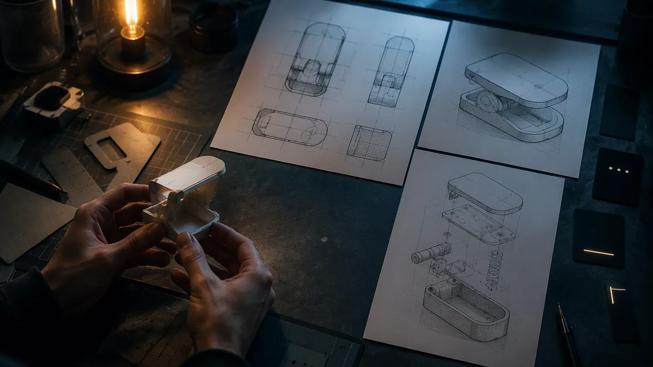
draw an original device in orthographic, isometric and exploded views to patent conventions, and build a quick card mock-up to check that the drawings describe a buildable object.
Instruction
This studio trains your hand and eye in the drawing language of inventors. You will draw your own device, or for practice an everyday medical object such as a pill organizer or a finger pulse oximeter, in three views, then build a card mock-up to test whether your drawings actually describe something that can exist.
Orthographic views. Imagine the object inside a glass box and look straight at each face. The front view shows height and width. The top view, drawn directly above the front view, shows width and depth. The right-side view, drawn to the right of the front view, shows height and depth. Because they are aligned, you can project lines between them with a ruler: the top of the object in the front view is at the same height as the top in the side view. Use a light pencil for construction lines and ink only the final edges.
Isometric view. An isometric drawing shows three faces at once. Draw a vertical line for the nearest corner, then two lines at 30 degrees from horizontal, one to each side. All three axes use the same scale, so measurements transfer directly from your orthographic views. Isometric graph paper makes this easy.
Exploded view. Separate the parts along the direction they assemble, with thin dashed lines showing how they fit. An exploded view of a pulse oximeter clip might show the top housing, the light source, the sensor, the spring and the bottom housing, spaced apart on a vertical axis.
Line and numerals. Use a consistent line weight for visible edges (a 0.5 mm fine liner) and a thinner line (0.1-0.3 mm) for lead lines and surface shading. Shading uses parallel lines, closer together on surfaces turning away from the light. Place reference numerals outside the drawing where possible, with lead lines that do not cross each other. Number parts in the order a reader will meet them in the description, often in tens (10, 20, 30) so you can add parts later (12, 14). Label each figure “FIG. 1” and so on. Keep numerals at least about 0.32 cm (1/8 inch) high, as the USPTO rules require.
Why a mock-up? Drawings can describe impossible objects without anyone noticing. Building a quick model from card and tape at the drawn dimensions reveals errors: a hinge on the wrong side, a part too thin to hold, a sensor the finger cannot reach. Correct the drawing to match what works. This is iteration in miniature.
Accessibility and ergonomics. As you draw a medical device, think about hands that shake, eyes that see poorly and users who are anxious. Large controls, high-contrast markings and tactile cues are design decisions you can show in the drawing.
📖 Read for this lesson
The reading opens over the lesson; close it to come back to exactly where you were. The checks below draw on it.
Studio: Three figures and a card mock-up
Question. Do my drawings describe my device clearly and correctly enough that a mock-up built from them alone, a day later, matches what I intended?
Materials
- Plain white drawing paper or bristol board and isometric grid paper
- Pencil, eraser and 0.1, 0.3 and 0.5 mm black fine-liner pens
- Ruler, 30-60-90 set square or protractor
- Thin card (cereal-box weight), masking tape and round-tip scissors
- A simple medical object for practice, such as a pill organizer, or the student’s own device concept
- Cut card with round-tip scissors. If a craft knife is needed, an adult demonstrates and stays present: use a cutting mat and a metal ruler, cut away from your body, and retract or cap the blade when not in use.
- Keep pens capped when not in use; fine-liner ink stains but is water-based.
- Sit with good posture and rest your eyes by looking into the distance every 20 minutes during detailed drawing.
Procedure
- Sketch your device freehand from several angles and list its parts with reference numerals in tens.
- Draw FIG. 1, a set of aligned orthographic views (front, top and right side), projecting construction lines between them.
- Draw FIG. 2, an isometric view on grid paper, transferring measurements from FIG. 1.
- Draw FIG. 3, an exploded view showing how at least three parts fit together.
- Ink the final edges at 0.5 mm, add lead lines and line shading at 0.1-0.3 mm, and label every figure and numeral.
- Set the drawings aside for at least a day. Then build a card mock-up from the drawings alone, as if someone else had drawn them, without looking at your sketches or notes. (Optional: a family member or other adult builds one from the drawings while you stay silent.)
- Compare the mock-up with what you intended, list every mismatch, and correct your drawings.
Data
| Mismatch found in the mock-up | Which figure caused it | Correction made |
|---|---|---|
Analysis
- How many mismatches did the mock-up reveal, and which view caused most of them?
- Which convention (alignment, numerals, exploded view, shading) did the most to make your drawings readable?
- What did building from your drawings alone, after a day away, teach you about what they leave unsaid?
- Where in your design did you show a decision about accessibility or ergonomics?
If you cannot do this studio in person: Draw the three figures on any paper with a ruler, or in Inkscape (free) using a grid, and build the mock-up from household card such as a cereal box.
Formative check
Work through these before moving on. They are not graded — they tell you whether the standard below has landed yet.
In aligned orthographic views, where is the top view drawn?
Numbering parts in tens (10, 20, 30) leaves room to add parts later, such as 12 and 14.
In an isometric drawing, the two receding axes are drawn at degrees from horizontal.
List the mismatches your mock-up revealed and the corrections you made. Which figure improved most after correction?
How confident are you that you can draw an original device to patent conventions in three views and test the drawings with a mock-up?
Practice
Work these on paper or in your notebook, then open Check your answer. Aim for all of Fluency and Application; try at least one Challenge.
Printable version: this unit’s practice workbook (PDF)
Fluency
Build speed and accuracy with the core skill.
- In aligned orthographic views, which two dimensions does each view show? (a) front; (b) top; (c) right side. Where is each drawn?
Check your answer
Answer: (a) Front: height and width. (b) Top: width and depth, drawn directly above the front view. (c) Right side: height and depth, drawn to the right of the front view.Alignment lets you project lines between views with a ruler. - Define isometric drawing, construction line, line weight and mock-up.
Check your answer
Answer: Isometric drawing: shows three faces with three axes at equal angles and a single scale. Construction line: a light guide line used to lay out a drawing. Line weight: the thickness of a line, used to separate edges, lead lines and shading. Mock-up: a quick physical model at the intended size, used to check form and fit.Construction lines are drawn in light pencil; only final edges are inked. - Give the line weights the lesson recommends for (a) visible edges and (b) lead lines and surface shading.
Check your answer
Answer: (a) 0.5 mm fine liner. (b) A thinner 0.1-0.3 mm line.Consistent weights separate edges from numerals’ lead lines and shading.
Application
Use the skill in context. Show your reasoning.
- A pill organizer is 20 cm wide, 4 cm deep and 3 cm tall. Give the dimensions shown in its front, top and right-side views. In an isometric drawing at full scale, how long are the three edge lines from the nearest corner?
Check your answer
Answer: Front: 20 cm wide by 3 cm tall. Top: 20 cm wide by 4 cm deep. Right side: 4 cm deep by 3 cm tall. Isometric: 3 cm vertical, 20 cm along one 30-degree axis, 4 cm along the other.Front shows height and width; top shows width and depth; side shows height and depth. All three isometric axes use the same scale, so measurements transfer directly. - Your device has parts numbered 10 (housing), 20 (sensor), 30 (spring). You add a light source that sits between housing and sensor and a hinge pin on the housing. Assign numerals that follow the lesson’s convention.
Check your answer
Answer: For example: hinge pin 12 (a sub-part of housing 10) and light source 14 or 16 (between 10 and 20). Any unused numbers between the tens are acceptable, in the order the reader meets them.Numbering in tens leaves room to add parts later. - Describe an exploded view of a finger pulse oximeter clip as the lesson does: which parts, and along which axis?
Check your answer
Answer: Top housing, light source, sensor, spring and bottom housing, spaced apart along a vertical axis, with thin dashed lines showing how they fit.Exploded views separate parts along the direction they assemble. - The USPTO rule requires reference characters at least about 0.32 cm (1/8 inch) high. Check the conversion: 1 inch = 2.54 cm. Is a numeral 3 mm high acceptable?
Check your answer
Answer: 1/8 inch = 0.3175 cm, about 0.32 cm or 3.2 mm. A 3 mm numeral is slightly too small; make it at least about 3.2 mm.2.54 / 8 = 0.3175 cm = 3.175 mm. 3 mm is less than that. - Your card mock-up shows the hinge on the wrong side, so the clip cannot open toward the finger. Explain why the lesson calls this iteration in miniature, and name one accessibility or ergonomic decision you could add while redrawing.
Check your answer
Answer: Building the mock-up tested the drawings and revealed an error, so you correct the drawing to match what works, a small prototype-test-improve loop. Accessibility example: larger controls or a high-contrast marking for users with shaky hands or poor eyesight, or a tactile cue.Drawings can describe impossible objects without anyone noticing; the mock-up catches it.
Review
Keep earlier skills sharp.
- Review 3.1: Which USPTO convention ties a part in FIG. 2 to the written description, and what kind of line connects it to the part?
Check your answer
Answer: Reference numerals, joined to the part by a thin lead line, matching the numbers used in the written description.Keep lead lines from crossing and place numerals outside the drawing where possible.
Drawing to Patent Standard: Sheet Limits, Projection Geometry and a Mock-Up Cut List
37 CFR 1.84 (eCFR, retrieved 2026-09-26); worked examples and cut list are SLS original; RLP at-home version 2026-11-10 · Public domain (37 CFR 1.84); SLS original (worked examples)
Why this reading. The lab has you draw an orthographic set, an isometric view and an exploded view, then check them by building a mock-up. This technique sheet gives real measurements: the sheet limits from the federal drawing rule, the projection geometry with a worked example, and a cut list for the card mock-up. Drawing rules are from 37 CFR 1.84 (public domain).
Sheet limits (37 CFR 1.84, eCFR retrieved Sept. 26, 2026)
Margins: top at least 2.5 cm (1 inch), left at least 2.5 cm, right at least 1.5 cm (5/8 inch), bottom at least 1.0 cm (3/8 inch). On 21.6 x 27.9 cm (8.5 x 11 inch) paper the drawing area is therefore no greater than 17.6 x 24.4 cm. Numbers, letters and reference characters must be at least .32 cm (1/8 inch) tall. Views must not be connected by projection lines and must not contain center lines, so erase or leave faint your construction lines in the final.
Worked example: a 60 x 40 x 20 mm block
| View | Shows | Size on paper at 1:1 | Where on the sheet |
|---|---|---|---|
| Front (FIG. 1A) | Width x height | 60 x 20 mm | Lower left |
| Top (FIG. 1B) | Width x depth | 60 x 40 mm | Directly above the front view, sharing its 60 mm width |
| Right side (FIG. 1C) | Depth x height | 40 x 20 mm | To the right of the front view, sharing its 20 mm height |
Check: the top view is 60 mm wide like the front view, and the side view is 20 mm high like the front view. That sharing of dimensions is what alignment means.
Isometric geometry, with numbers
In an isometric drawing, the two receding axes run at 30 degrees from horizontal and all three axes share one scale. For a cube with a 40 mm edge, each edge is drawn 40 mm long. The outline’s width is 2 x 40 x cos 30° = 69.3 mm (cos 30° = 0.866), and its height is 40 + 2 x 40 x sin 30° = 40 + 40 = 80 mm (sin 30° = 0.5). On isometric grid paper, the grid lines already run at 30 degrees; count squares rather than measuring angles.
Line weights and numerals
Ink the outer edges at 0.5 mm, lead lines and shading at 0.1 to 0.3 mm. Number parts in tens (10, 20, 30) so parts added later can be 12 or 14. Put each numeral at the end of a short lead line that does not cross another lead line.
Card mock-up cut list for the block
| Piece | Size (mm) | Count |
|---|---|---|
| Front and back | 60 x 20 | 2 |
| Top and bottom | 60 x 40 | 2 |
| Left and right | 40 x 20 | 2 |
Total surface area = 2(60×20) + 2(60×40) + 2(40×20) = 2,400 + 4,800 + 1,600 = 8,800 mm2. Set your drawings aside for a day, then build the block from your three views alone, without your sketches or notes (or ask a family member or other adult to build it from the drawings without your explaining). Log every mismatch in the lab’s table.
Sources: 37 CFR 1.84, Standards for drawings (ecfr.gov)